Categories
Electronic upgrades Multicopter

Telemetry mod for DJI Phantom 1

After my Y6-Copter with APM, I also want to see telemetry data of the Phantom 1, which isn’t capable on its own to transmit any data.

The original PPM receiver (Single antenna) got swapped by a FrSky XRS, which is amazingly small and has PPM, S.Bus and S.Port.

The translation between Naza-GPS and S.Port is done by an arduino nano which is connected to FrSky-S.Bus on Pin9 and to GPS Tx on Rx (also power from the receiver cable).
I used the software by Alezz in this thread but had to make some changes to get it running. My changed version is online at GitHub.

Here are some Pictures of the harness with the arduino and the Installation in the Phantom 1.

  • OLYMPUS DIGITAL CAMERA
  • OLYMPUS DIGITAL CAMERA
  • OLYMPUS DIGITAL CAMERA
  • OLYMPUS DIGITAL CAMERA
  • OLYMPUS DIGITAL CAMERA

I didn’t want to cut the GPS connector, so I just pushed a jumper wire in the connector.
That was initially just for testing but made such a solid connection that this will stay in there.

  • OLYMPUS DIGITAL CAMERA
  • OLYMPUS DIGITAL CAMERA

The GPS Format in Degrees+Minutes formatted as DDMM.MMMM.
So 1234.5678 means 12°34.567′

I still have some trouble with the GPS coordinates, sometimes just the Longitude will be transmitted and Latitude is just 000 but this will be updated as soon as I get further.
Also I’m a little confused about the “Alt” “Galt” and the “Alt” on the GPS screen. They all differ, but I will observe that during flight and remove the ones I won’t need from the arduino code.

Categories
Electronic upgrades Multicopter

Telemetry mod for APM and FrSyk X-Series (X4r)

After the Telemetry mod of the Turnigy 9x, the air-side has to be able to communicate, too.

Because the APM is not able to speak the FrSky-Protocol itself, a converter is needed to translate the data. There are several projects out there, mostly using a teensy. I decided to use rotcehdnih’s version, which is also cabable of running on an arduino nano or micro.

This is quite simple, just burn that softwre to an arduino (I’m going with an arduino pro micro), connect RX to the TX of the telemetry port and pin 9 to the S.Port of the FrSky receiver. Then just add some power (from the APM Telemetry port for example) and there you go!

  • OLYMPUS DIGITAL CAMERA
  • OLYMPUS DIGITAL CAMERA
  • OLYMPUS DIGITAL CAMERA
  • OLYMPUS DIGITAL CAMERA
  • OLYMPUS DIGITAL CAMERA
Categories
Electronic upgrades Multicopter

Telemetry mod for the Turnigy 9x an FrSky XJT Module

Hey Guys,

today I modded my Turnigy 9x to be able to receive Telemetry date via the FrSky XJT module.
There are many Telemetry mods for the 9x out there but most of them for the DJT or DHT module which use a serial connection on the ground side. The XJT also has a S.Port wich is already connected to the internal 5-pin connector. This makes any modification to the module unnecessary.

Like on the serial mod, you have to free up the UART pins on the 9x processor which are used by the two lower rear switches. In the images you can see that I did already connect the ISP Pins for flashing new Firmware to the 9x. Then I cut the traces for the most left resistors and connected them to the unused pins 41 and 42.
The two freed pins (RX) and (TX) are again getting connected to the ISP pin. Pin 2 will also be our S.Port pin.

  • OLYMPUS DIGITAL CAMERA
  • OLYMPUS DIGITAL CAMERA
  • OLYMPUS DIGITAL CAMERA
  • OLYMPUS DIGITAL CAMERA
  • OLYMPUS DIGITAL CAMERA

Important Note: Don’t do the mod like I did. Just desolder the two resistors and replace them with wired 120Ω one. So you don’t have to cut any traces and this makes soldering a lot easier.

Now we need to create a little circuit for inverting the S.Port signal (not quite sure if this is necessary, but it worked for me!):

  • OLYMPUS DIGITAL CAMERA
  • OLYMPUS DIGITAL CAMERA
  • OLYMPUS DIGITAL CAMERA
  • schematics

The S.Port is connected to pin 5 of the internal connector between the 9x and the module. This pin is unused and connected to the large solderpad. (Don’t know what it was supposed to be). I just connected the signal cable to the large solder pad.

  • OLYMPUS DIGITAL CAMERA
  • OLYMPUS DIGITAL CAMERA

Now the inverter PCB hast to be connected to the processor. Signal to MOSI, power to 5V and GND to GND:

  • OLYMPUS DIGITAL CAMERA
  • OLYMPUS DIGITAL CAMERA
  • OLYMPUS DIGITAL CAMERA
  • OLYMPUS DIGITAL CAMERA

I also wrapped the PCB in duct tape to insulate it.


That’s the hardware side.

I used the er9x Firmware in the FrSky version wich uses the changed switch pins and enables telemetry. You can download the firmware and the flashing utility from the er9x webside. Remember to save / write down your settings before flashing.
To get the 9x to listen to S.Port instead of RX/TX, you have to set the protocol to PXX. Now you should already be able to see the RSSI values.

REMEMBER to rebind the receiver if you switched from another protocol to PPX.

Categories
Multicopter

Repairing an old broken DJI Phantom

I recently bought a cheap broken DJI Phantom 1 and would like to show you the process of analyzing and repairing the drone.

There were multiple problems, I will explain them one by one.

1. Phantom drops down when tilting

Problem

Here you can see that the phantom is hovering quite nice, but in the forward flight it suddenly falls down, all LEDs went off.

Cause

The Phantom has an internal USB cable which is connected to the microUSB port of the LED-module. This cable usually is hold in place by a cable tie and is accessible by the battery door.
In this phantom, someone removed that cable tie and the cable was flying around loosely, causing a short on the solder points of the battery connector or the power line for the speed controllers.

Solution

Fixed the cable with a cable tie. – Easy one…

2. Copter falls again midair

Problem

The Copter falls down while hovering, all LEDs stays on and starts beeping.

Cause

  • OLYMPUS DIGITAL CAMERA
  • OLYMPUS DIGITAL CAMERA

The X3 connector from the PMU-board to the Naza is the power source for the flight controller. The red wire is the +5V line which has a loose connection on the board, although covered in the white protective glue.

Solution

I simply replaced the cable with a new one…

  • OLYMPUS DIGITAL CAMERA
  • OLYMPUS DIGITAL CAMERA

Easy to fix, hard to find.

3. Copter wobbels in ATTI mode – (really easy one)

Problem

When flying in ATTI-mode (Stabilized, without GPS), the copter starts to shake and wobble.

Cause

The previous owner changed the default board with the PMU-One for a zenmuse gimbal. The Naza (which contains the gyro sensors) is usually glued to the board with foam pads.
In this case, it was glued with superglue, wich won’t adhere to the coated PCB. So the Naza became loose and was just hold by the cables. I was impressed how stable it stays with this in GPS mode!

Solution

Fixed the Naza with foam tape.

4. Phantom randomly switches from GPS to ATTI mode

Problem

During a GPS flight, the LED randomly turns yellow for a few seconds and the copter starts drifting which means that it switched to ATTI mode.

Cause

  • img_20161015_145426
  • img_20161015_145531
  • img_20161015_145840

In the upper shell of the phantom is the GPS module which contains the antenna. To reduce interferences from the regulators, it is shielded with a rubber coated copper foil.
This foil was lacerated and the the copper foil wasn’t insulated on some parts. These touched the GPS module and randomly caused it to fail.

Solution

Just added some duct tape as insulation between the module and the copper foil.

Now, it seems to fly very stable and reliable. There are already further modifications queued…

Categories
CAN-BUS Car mediacenter

Project MPi3 – New housing and published all source code

Previous: Display additional data


Hey there, I finally managed to upload source files for my Project!

Program at GitHub

Housing at thingiverse

The program currently listens for the previously mentioned diagnostic data. The Requests are send outside the program. I will change that when i figure out how to get the data without activly asking for them. Just by observing the bus.

  • In
  • Bottom
  • IMG_20151106_174410
  • IMG_20151106_175827
  • IMG_20151106_175846
  • IMG_20151106_180004
  • IMG_20151107_121508
  • IMG_20151107_121432

As you can see above, there is also a housing for the raspberry and the other components. The system is now installed hidden in my car, directly connected to the entertainment bus and the aux-in of the headunit.

The Connection is made with a 15-pin d-sub connector as follows:

MPi3

The audio in connects to the audio out of my tv receiver, the 12V are from the power source for the interrior lighting. This line will be activated when the car gets unlocked and stays active for about 30 minutes after locking the car. So the components won’t stay active all the time and drain my battery but will be available as soon as I enter the car.

  • IMG_20151107_113557
  • IMG_20151107_113642
  • IMG_20151107_130826
  • IMG_20151107_095606

My 12V USB adapter has two USB-ports. One was dissoldered and connected directly to the raspberry solder-pads PP1 and PP3. The other one is connected to my 4G-Router outside of the housing.

The Soundcard is also directly soldered to the Raspberry PP7 (+5V), PP42 (D-), PP45 (D+) and PP40 (GND).


For now I am really satisfied with this build although it is not yet ready. But becaus of that, the next update might still take a lot of time. Sorry for that…


Next: Capture the values without activly asking, upload the values and create nice graphs with them.

Categories
CAN-BUS Car mediacenter

Project MPi3 – Display additional Data

Previous: Fully working prototyle


With a controller connected to my Vehicles CAN-bus, I don’t want to limit the use of it to song-title and music controls. So I started to look for some more interesting values to get from the bus.
Sadly the “MS-CAN” (entertainment bus), which I am connected to cause of the info display, doesn’t allow communication to the ECU (also, this factprevents me from messing with the engine or other critical components).

The components connected to the bus do have some interresting informations and GM built a diagnostic protocol that lets you ask the controller for the actual values. This leads to the folling data:

248 # 06 AA 01 01 07 10 11 - Ask the A/C controller (0x0248) for measuringblocks 01, 07, 10 and 11
Answer:
548 # 01 03 A5 00 00 01 9C 00 - 01: 0x03A5: Solar sensor: 4.665V - 0x019C: Indoor temp sensor: 2.06V
548 # 07 00 90 04 3D FE 70 00 - 07: 0x90: Voltage: 14.4V
548 # 10 00 91 02 B2 03 1E 96 - 10: 0x0091: Out-temp: 14.5°C - 0x02B2: Engine temp: 69.0°C
548 # 11 08 ED 00 30 01 FE 23 - 11: 0x08ED: RPM: 2285 - 0x30: Speed: 48 km/h - 0x23: LED: 35%

The described values are only the ones that I already figured out.

My software now listens for this data on the bus and writes the values on the display.

  • IMG_20150927_123647

The displaymode can be switched with the number keys on the headunit (which are also unused in aux mode)


Next: New housing and published all souce code

Categories
CAN-BUS Car mediacenter

Project MPi3 – Fully working prototype

Previous: Music-Player gets CAN-BUS!


Since a very long break caused by many other projects going on, here is now another update.

The System is now functional and works pretty well.
Most important change: The projects now has a Name: “MiP3” (Raspberry Pi based MP3 Player… got it? Yeah, I know…)
Before the technical details, here directly the usage:

There are four play modes:
– My music
– My girlfriends music
– Carpool (society-compatible) music
– Audio from TV-Receiver (DVB-T – The non-american version of ATSC)

  • IMG_20150902_203204

The playlist is switched by pressing the (in AUX-Mode unused) steeringwheel-down button. Holding the button will activate the TV-audio-mode.
By pushing the up button, the song will be skipped and the skip will be marked in the database. Holding up will delete the current song from the actual playlist.
New music will be added to all playlists and stays there until it is removed. So in the beginning, all music was played in all modes. But after two months now, the playmodes fit verry well. I currently have about 20GB of music installed.
There is no chance to play one particular song, this is by design because I wanted to have it more “radio-like” where I can just take slight influence on the music.

When the TV-audio is activated, the sound from the audio-in of the USB-Soundcard will be played with “alsaloop”.


Next: Display additional data


Categories
CAN-BUS Car mediacenter Electronic upgrades

Music-Player gets CAN-BUS!

Lets’s get deeper in the car’s electronics

My XBMC-Mediacenter works pretty well. But the only way to skip a song is the I/R remote placed in my armrest and to see what song is playing, I need to switch the whole display to mediacenter mode.
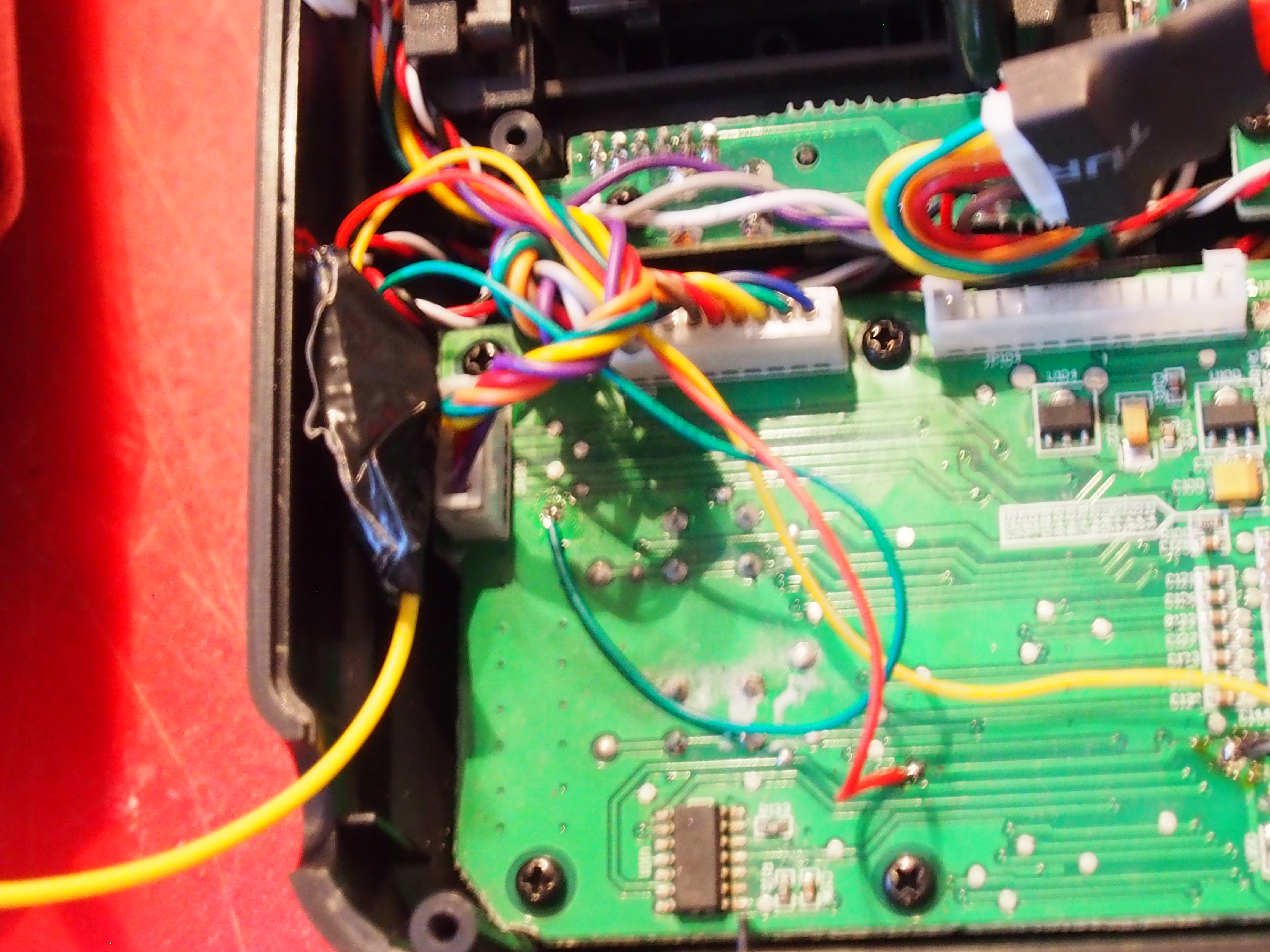
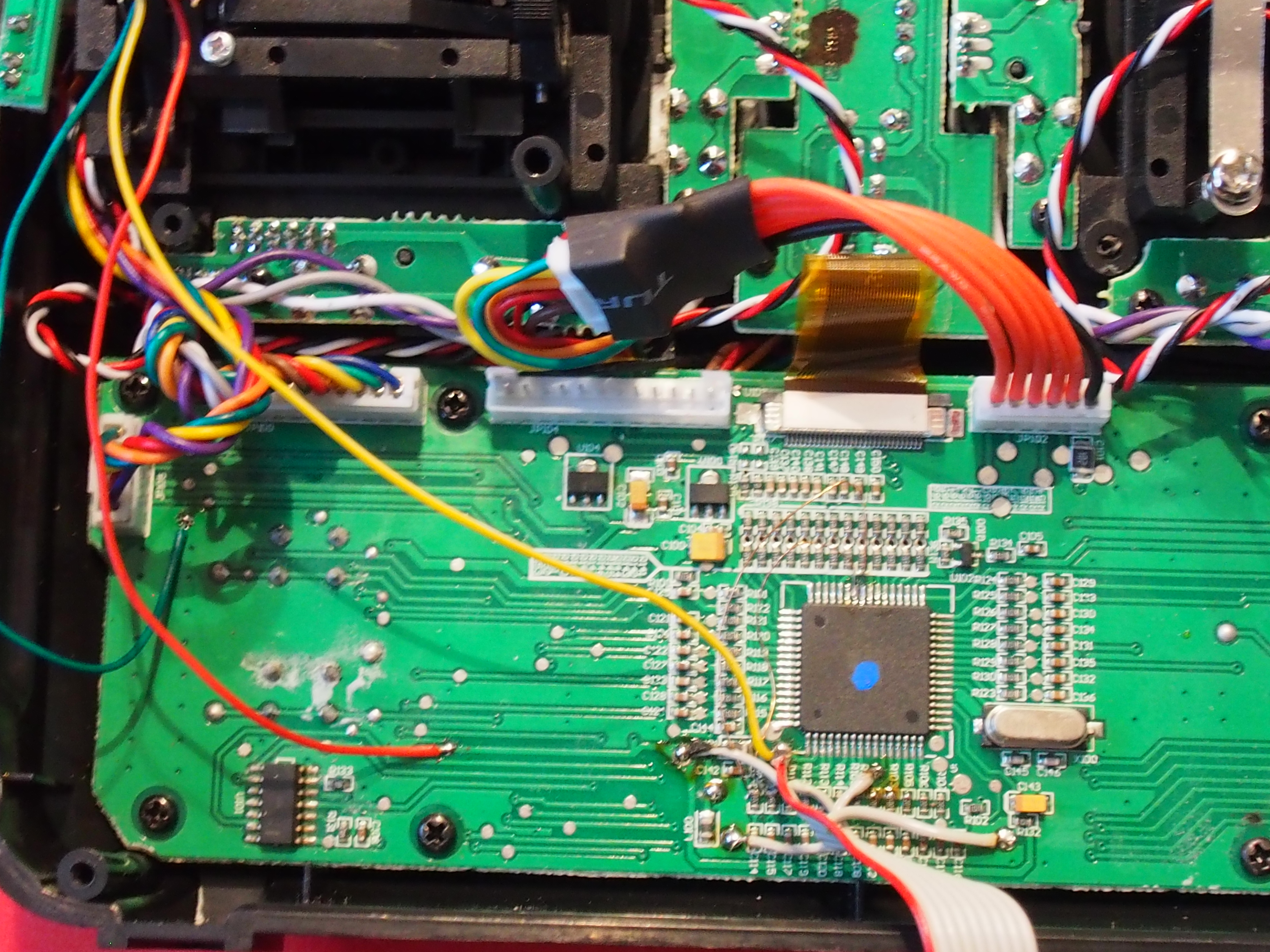
Because I always wanted to take a closer look at the CAN-BUS in my opel astra, I decided to give the music player another update.

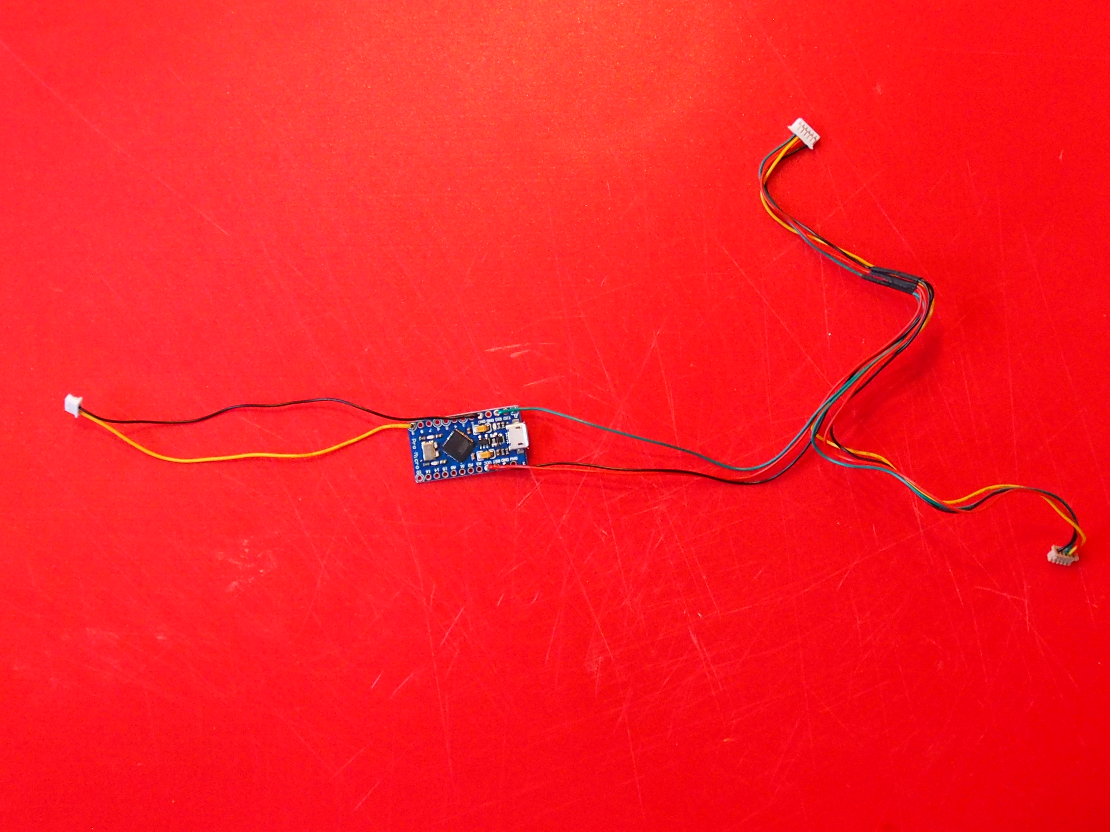
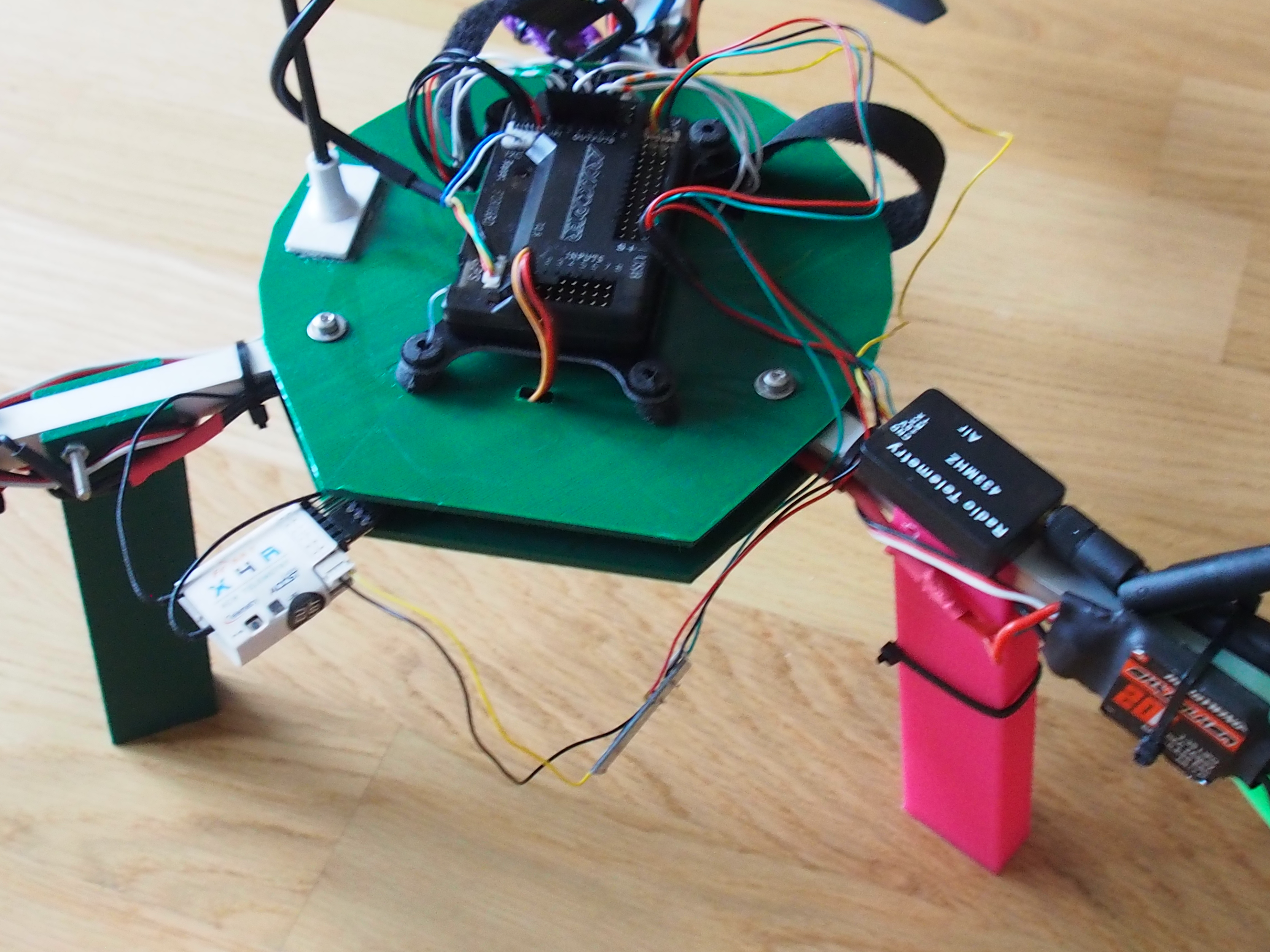
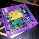
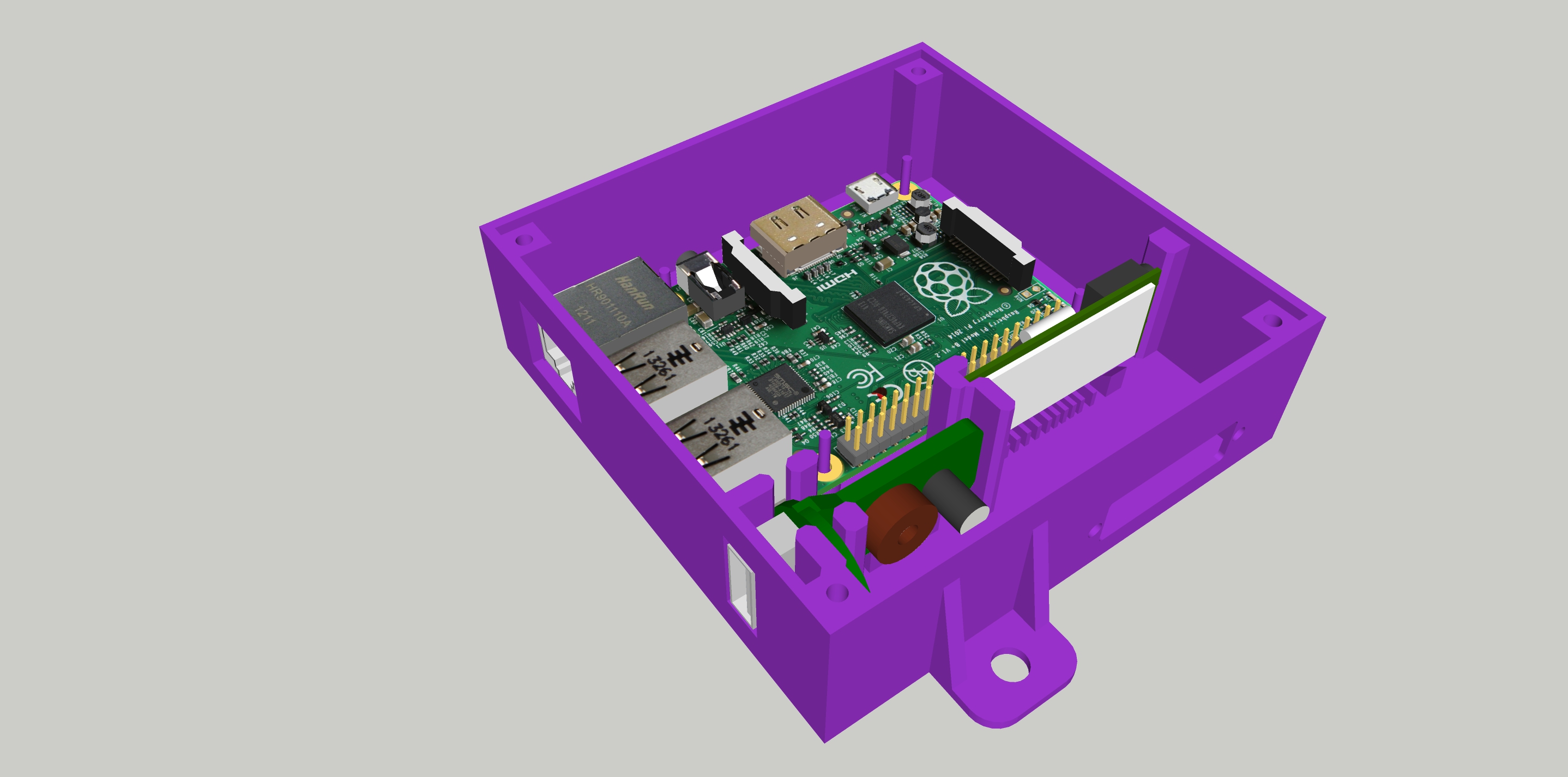
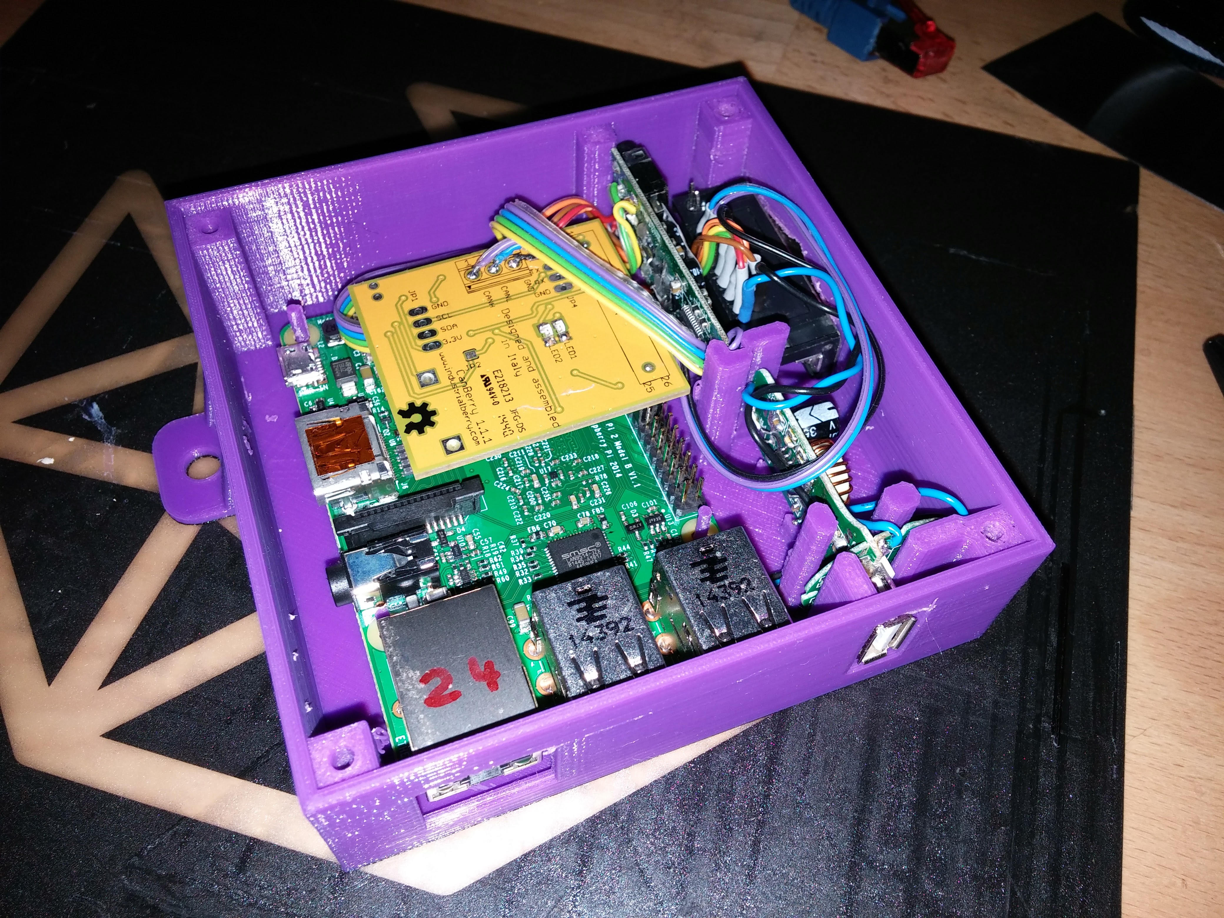
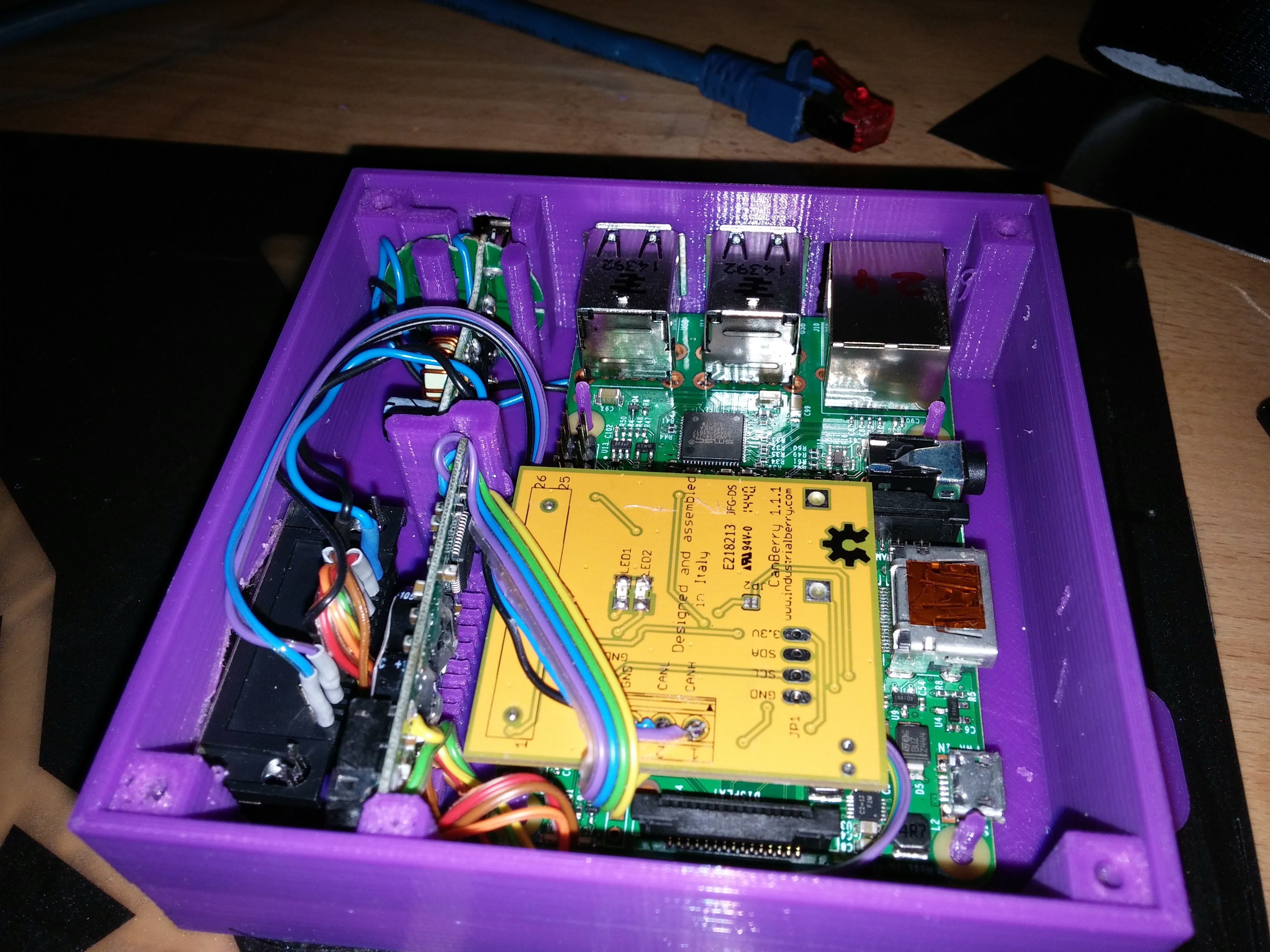
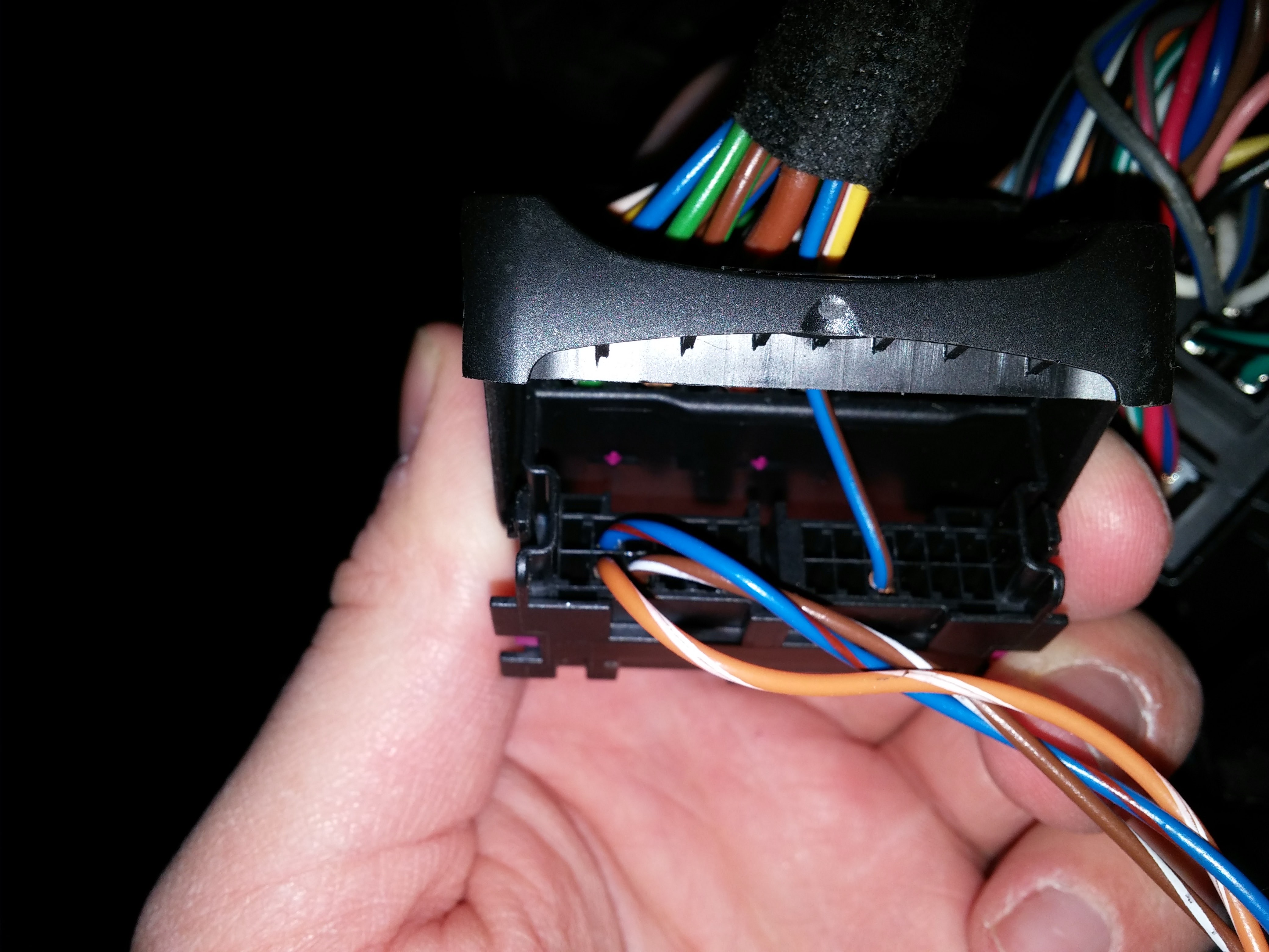
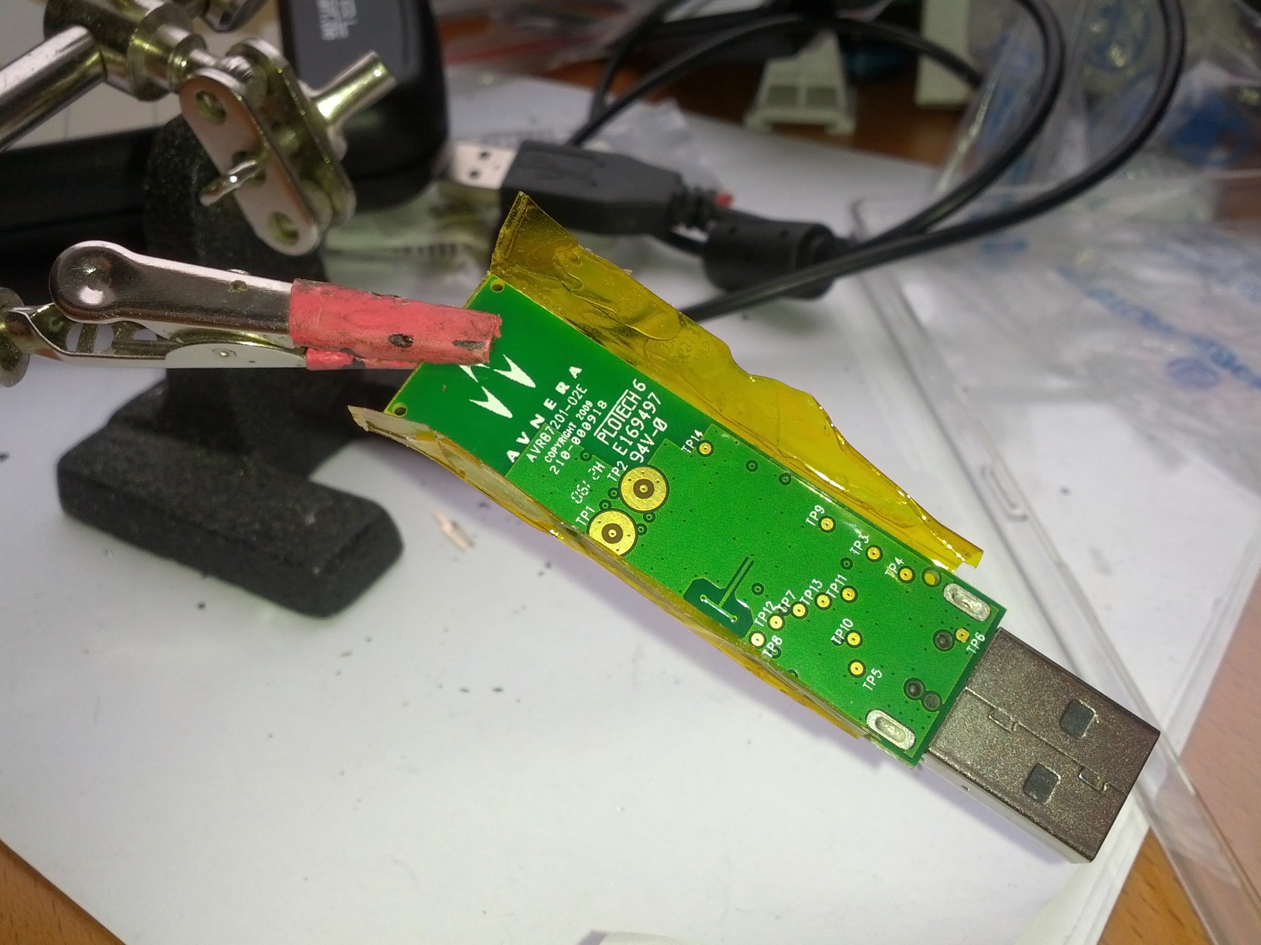
So I ordered a MCP2515 / MCP2551 CAN-BUS interface for a raspberry pi and started to scan the bus.

The opel astra h (2004-2010) has the following busses:

  • SW-CAN (SingleWire) 33.3 kbps also known as “GMLAN”
  • MS-CAN (MidSpeed) 95.0 kbps
  • HS-CAN (HighSpeed) 500 kbps

The car body bus

The first was to capture some “base noise” with the bus awake and the ignition off. Then I performed some actions like pressing buttons, locking/unlocking the car etc.
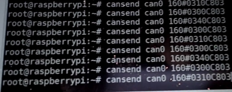
That capture could be compared to the base noise to identify the messages only send in that capture. That gave me some results:

CAN_Key_Commands

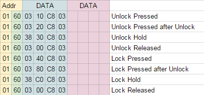
This means that when I send 160#0340C803, followd by 160#0300C803, the car locks! This point was a huge milestone!

  • can_lock

The entertainment bus

What I really was interested on was the MS-CAN with the unusual 95 kbps!
So I did the same as above and found what I wanted:

206 # 01 91 00 - Steering Remote UP
206 # 01 92 00 - Steering Remote Down

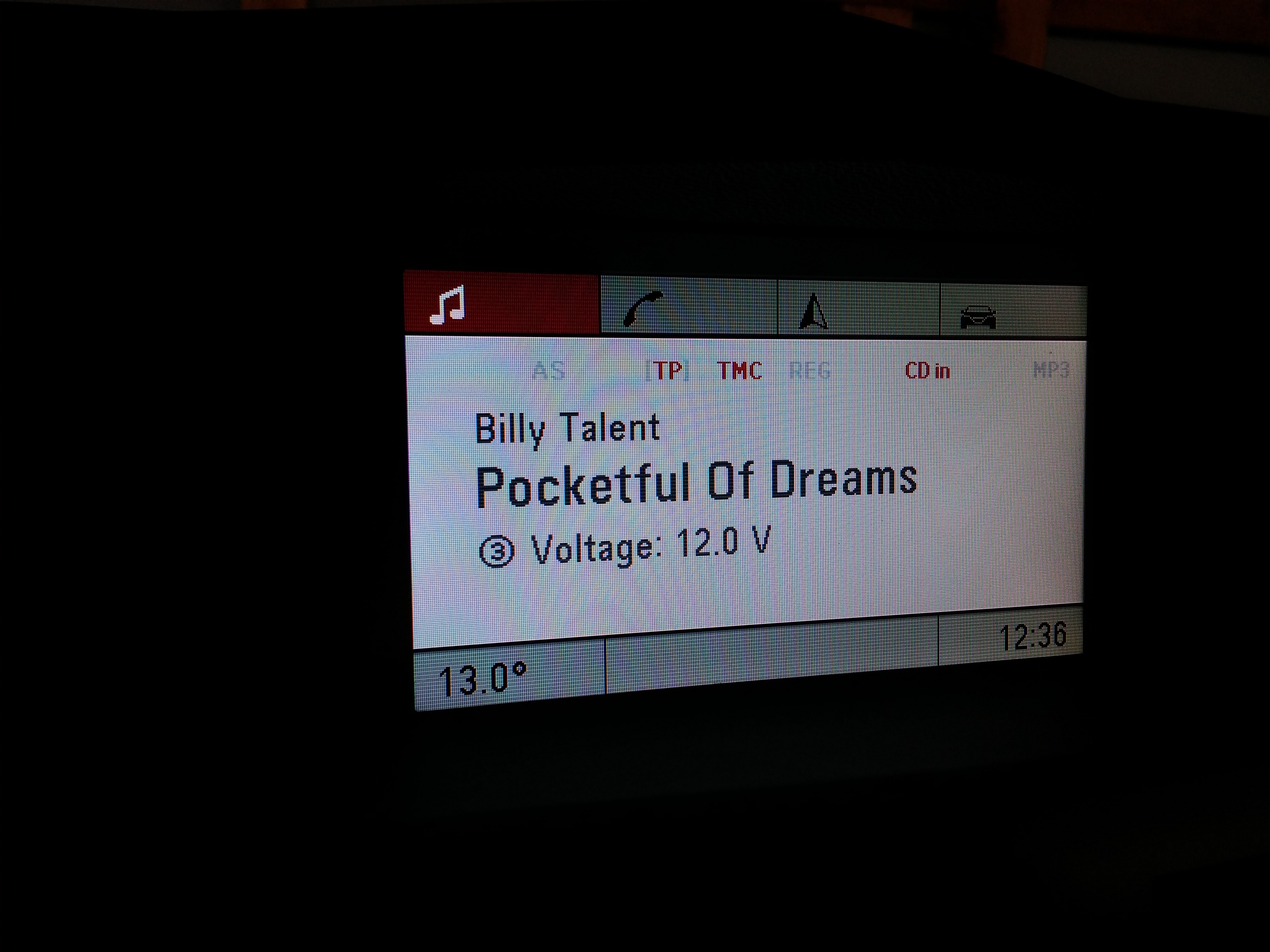
I also found the outdoor temperature:

683 # 46 01 XX where the temp in celsius is XX/2-40 so 0x00 is -20.0°C and 0x76 is 19.0°C.

But the really cool data goes to the display:

6C1 # 10 2E C0 00 2B 03 01 01
6C1 # 21 00 20 23 03 00 41 00
6C1 # 22 75 00 78 10 0A 00 1B
6C1 # 23 00 5B 00 66 00 53 00
6C1 # 24 5F 00 67 00 6D 00 41
6C1 # 25 00 75 00 78 11 01 00
6C1 # 26 20 12 01 00 20 01 00

The first byte of the packet identifies a multi-packet message. It starts with 0x10, than follows 0x2X where X increments from 1 to F. So after 0x2F comes 0x20, 0x21…
The second Byte of the first packet is the number in Bytes. The last packet is always 8 Byte long but the rest is ignored (these are either filled with 0x00 or the same then the previous package).
Than are two byte of command or mode. This is 0x4000, 0xC000, 0x5000 or 0xA000. Don’t know what that means… Than comes the size and type of the following container. Type 0x03 seems to update the main screen.
Now follow some strings, starting with an ID (here 0x01,0x10,0x11 and 0x12), the number of characters and the characters in UTF-16 (where only very vew unicode-chars are supported but that comes in the next post).

That’s all…

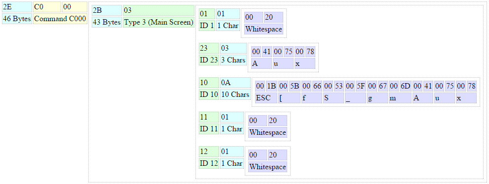
This is a schematic view of the above packet:

  • CAN_schematic


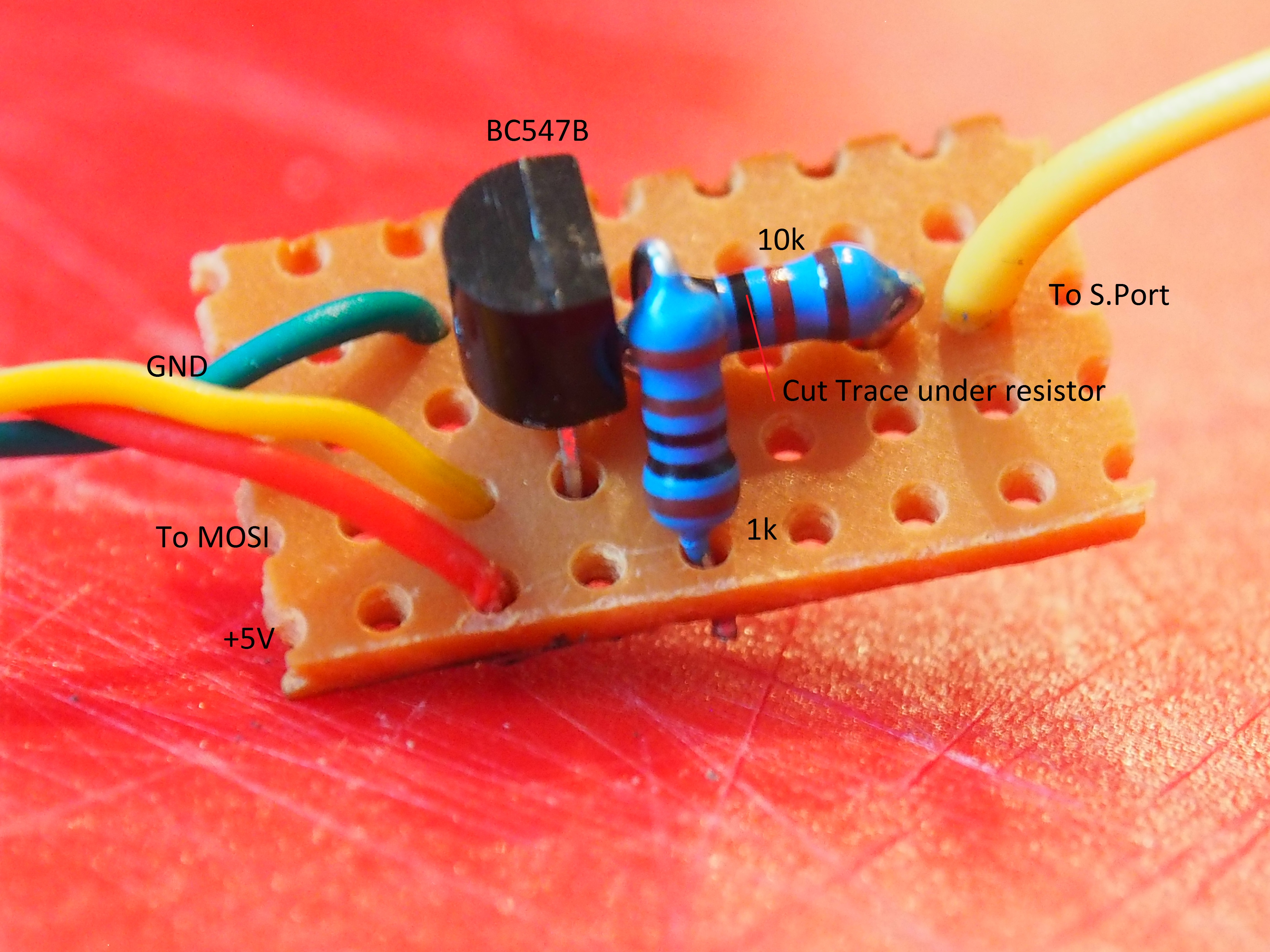
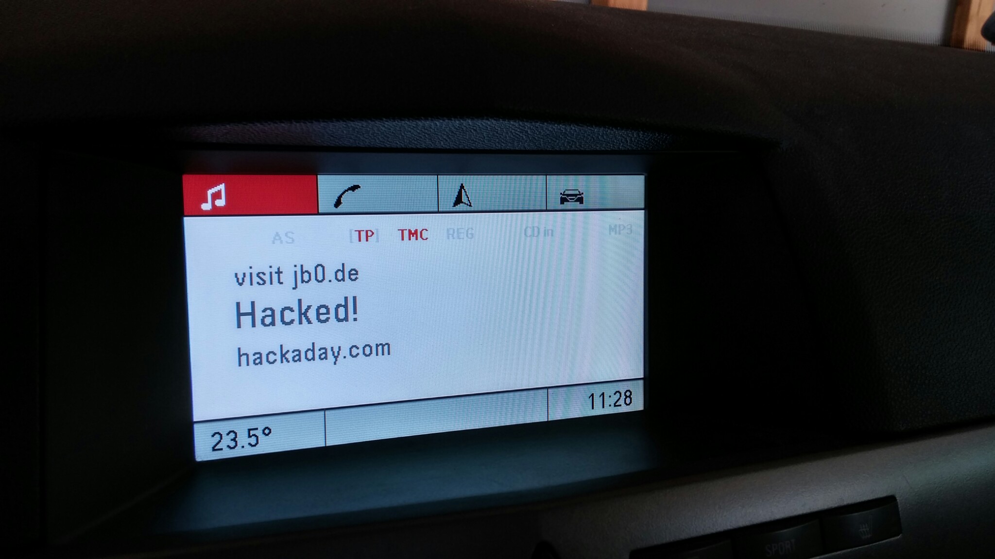
With that knowledge, I generated my own packet:

6C1 # 10 54 C0 00 51 03 01 01 - 84 Bytes, mode 0xC000, 81 Bytes payload, type 0x03, id 0x01, 1 char
6C1 # 21 00 20 02 03 00 41 00 - Whitespace, id 0x02, A
6C1 # 22 75 00 78 10 07 00 48 - u x, mode 0x10, 7 chars, H
6C1 # 23 00 61 00 63 00 6B 00 - a, c, k
6C1 # 24 65 00 64 00 21 11 0C - e, d, !, id 0x11, 12 chars
6C1 # 25 00 76 00 69 00 73 00 - v, i, s
6C1 # 26 69 00 74 00 20 00 6A - i, t, Whitespace, j
6C1 # 27 00 62 00 30 00 2E 00 - b, 0, .
6C1 # 28 64 00 65 12 0C 00 68 - d, e, id 0x12, 12 chars, h
6C1 # 29 00 61 00 63 00 6B 00 - a, c, k
6C1 # 2A 61 00 64 00 61 00 79 - a, d, a, y
6C1 # 2B 00 2E 00 63 00 6F 00 - ., c. o
6C1 # 2C 6D 00 00 00 00 00 00 - m

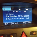
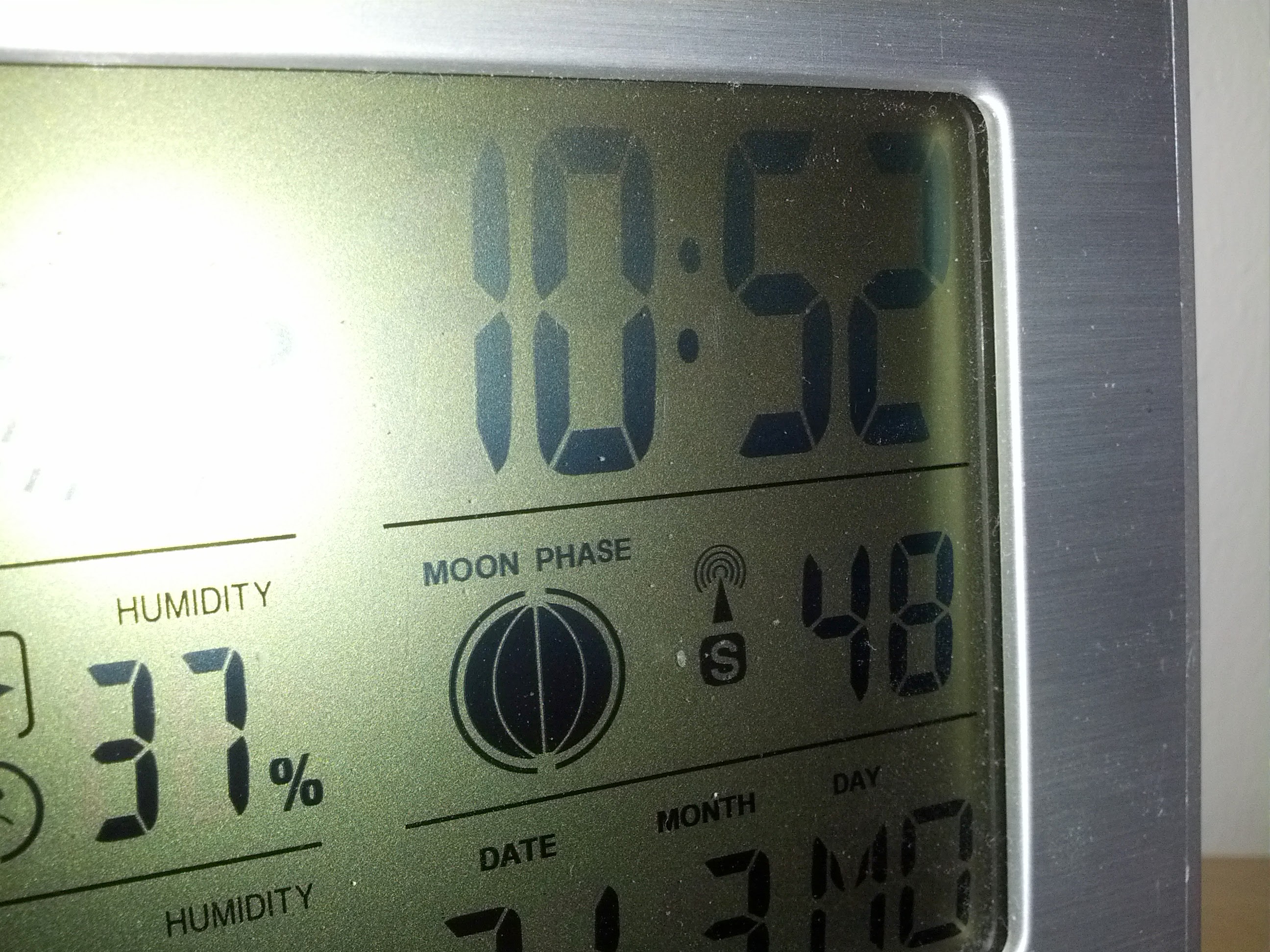
And what happened? This:

  • 20150703_112814_HDR


Next: Fully working prototype

Categories
Electronic upgrades

External Antenna for Logitech G930 headset

My Logitech G930 is a very cool headset but sometimes has little connection problems.

The solution offered by logitech is to change the frequency but in my case the problems seams independent to the frequency.
I have some 2,4 Ghz antenna stuff from older WiFi projects lying around and decided to take a clother look to the transmitter.
What I found are two PCB-antennas and two coax test points, so i took a RP-SMA pigtail, connected it to one of the test points, cut the connection to the PCB-antenna and attached it on the casing:

  • IMG_20140331_135829
  • IMG_20140331_140523
  • IMG_20140331_135836
  • IMG_20140331_141100
  • IMG_20140331_143016

I can’t yet say if the connection problems are solved with this, but the range is significantly better with the antenna!

There was two antennas inside the transmitter and I have no idea if they are diversity or one sends and the other receives or what they are for.
But when I have another matching pigtail in hands, I will connect the other one too…

Categories
Electronic upgrades

Retrofit radio controlled clock

Last sunday, germany switches to the daylight saving time again, so i needed to adjust some clocks.

We had a weathers station with wireless temperature and humidity sensors that has a clock which needs to be adjusted manuall while most of that weather stations have radio controlled clocks integrated.
Even my very cheap weather receiver which i got from a giveway and was only used to analyze the wireless temperature signal has a time receiver.

So i wondered if it is possible to put the receiver from the cheap weather station in the one we are using. Quickly opened it and found four empty soldering pads labled “RCC” – maybe radio controlled clock or something like that. Also the four pads itself are labled:

GND – Ground
VDD – Voltage source (3V)
PON – Power on Signal (3V)
TCO – TimeCOntrol? At least a data pin..

The labeling matches with the sensor, so i simply connected it:

  • IMG_20140330_140224
  • IMG_20140330_140237
  • IMG_20140330_140904
  • IMG_20140330_140207
  • IMG_20140330_140216
  • IMG_20140330_141438

Near the connector are two soldering Jumpers (S1 and S2) which are explained on the PCB and must be switched from S1 to S2.
Also there are two empty component places, usually used for the receiver which doesn’t exist on the source PCB:

R16: Pull-down resistor for the PON signal. This is already implemented in the receiver module
C12: Filter capacitor for the data signal – maybe not needed.

So both stay empty.

The case has already mounts for the antenna where my antenna exactly fits in!

At least everything is put back together and six minutes later:

  • IMG_20140331_105247

The time is synced! And again one less clock to adjust!