Categories
Electronic upgrades Multicopter

Telemetry mod for DJI Phantom 1

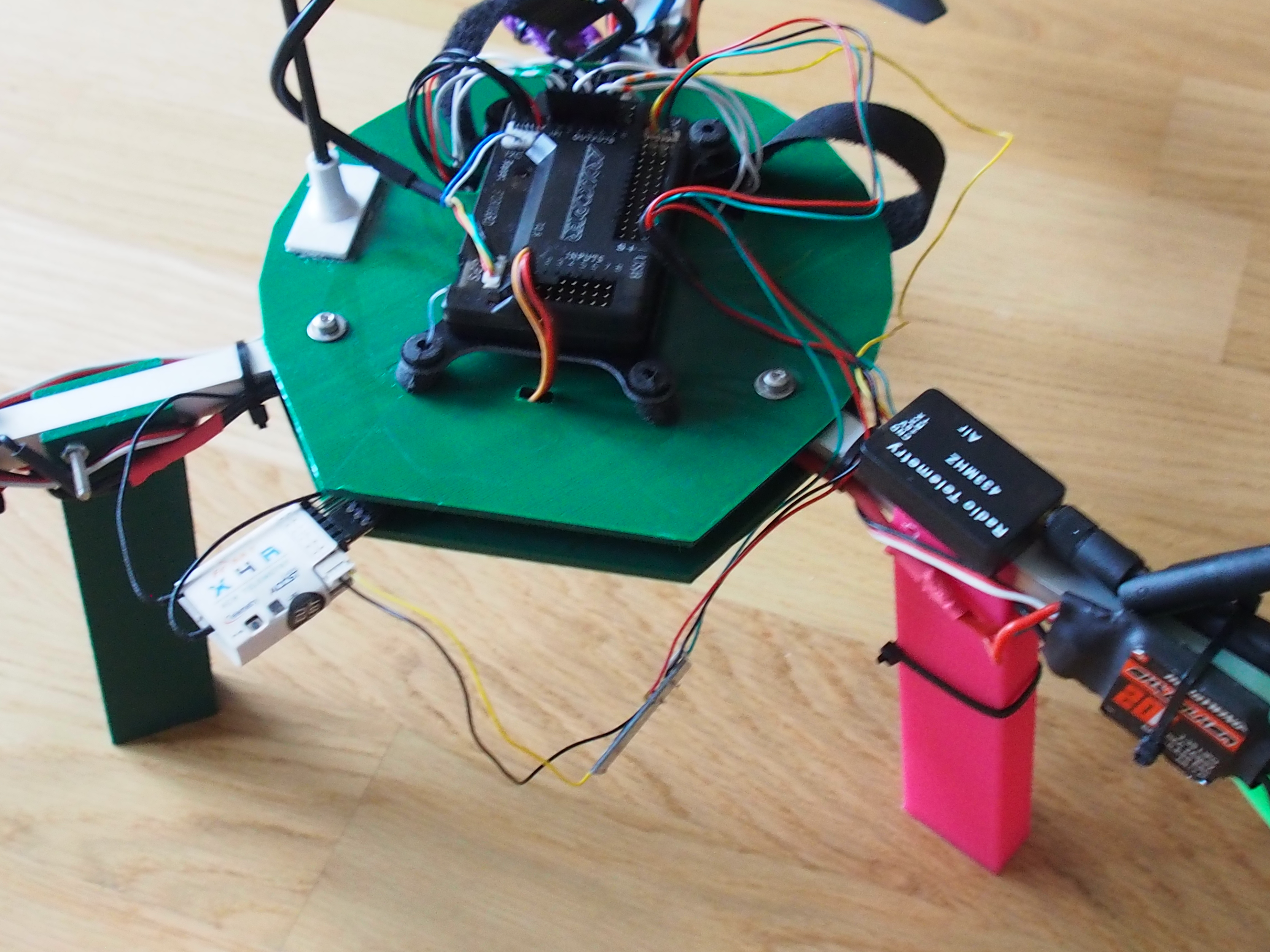
After my Y6-Copter with APM, I also want to see telemetry data of the Phantom 1, which isn’t capable on its own to transmit any data.

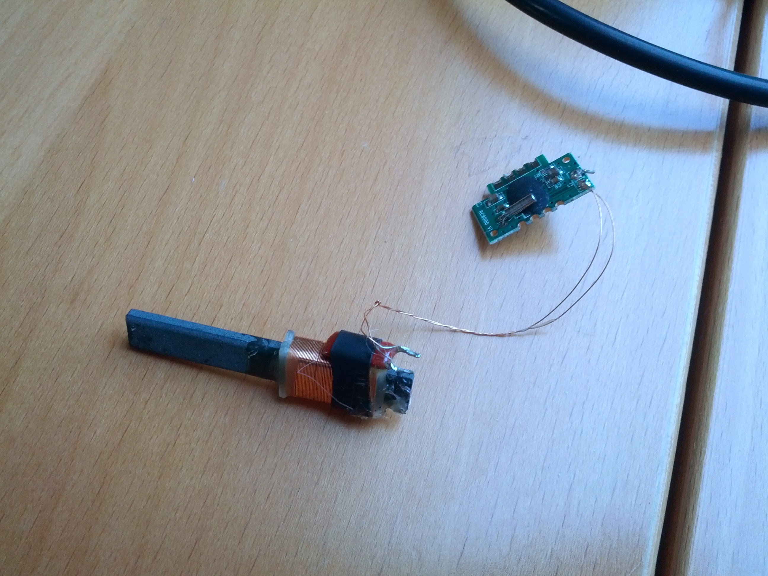
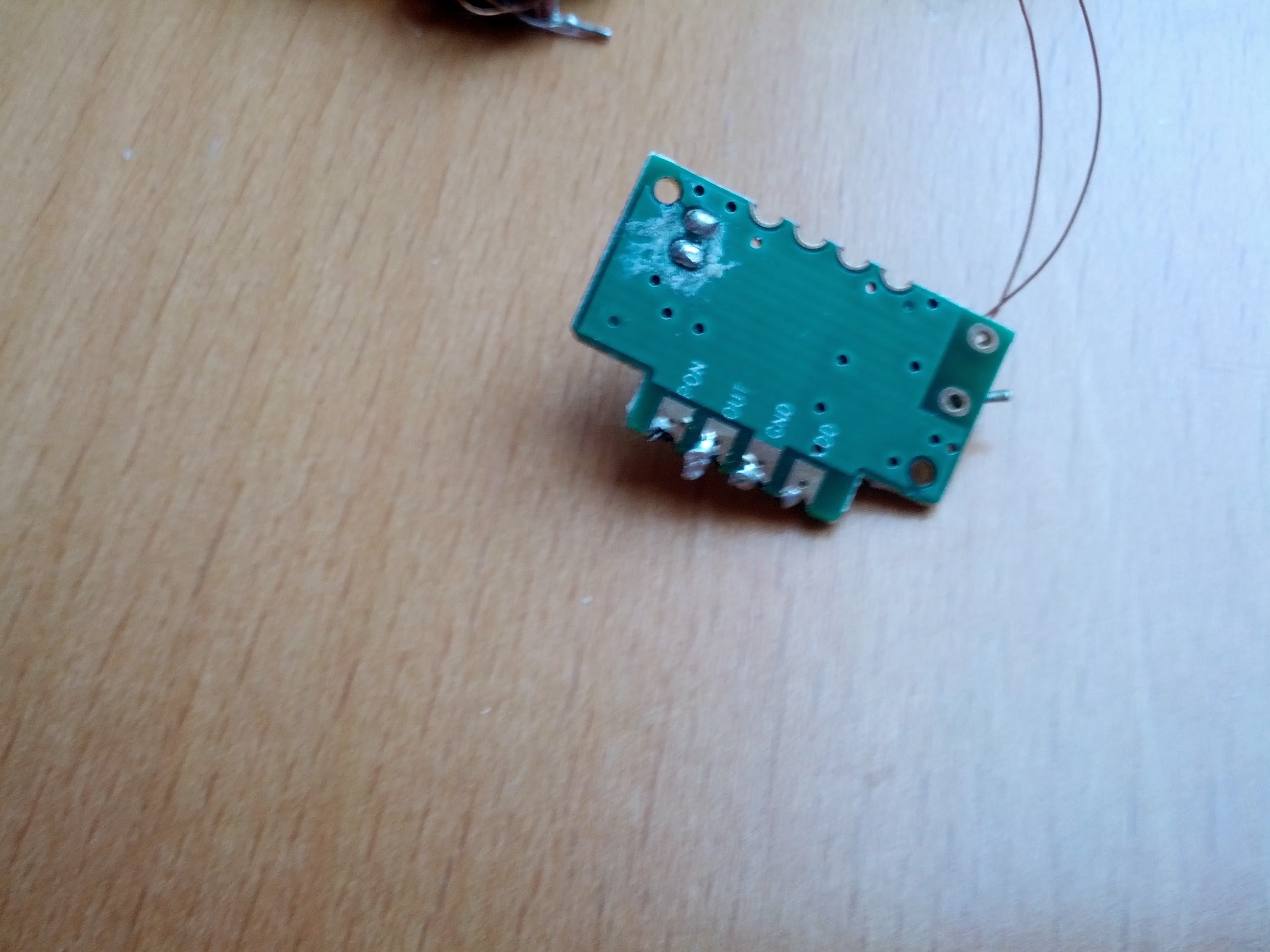
The original PPM receiver (Single antenna) got swapped by a FrSky XRS, which is amazingly small and has PPM, S.Bus and S.Port.

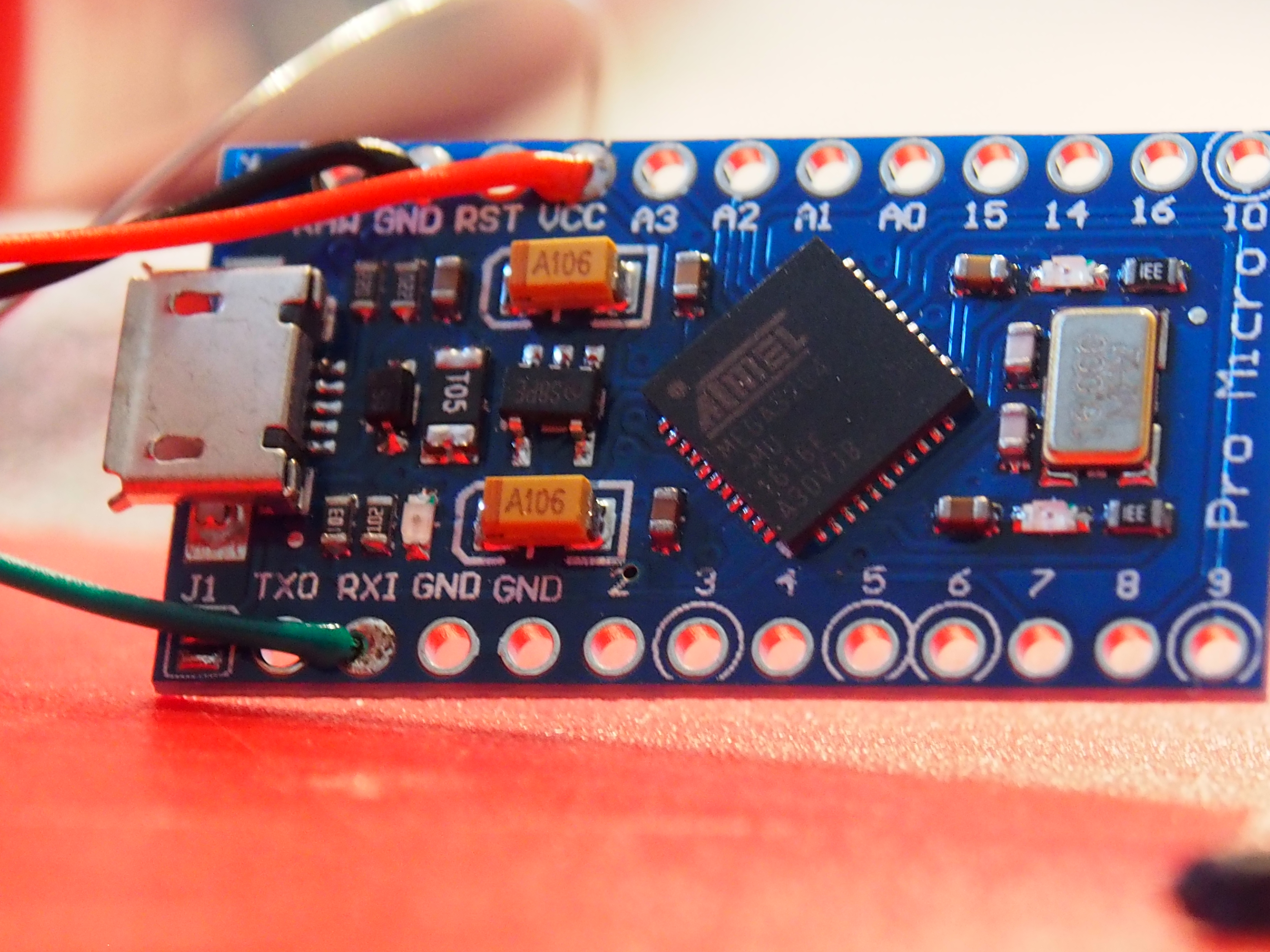
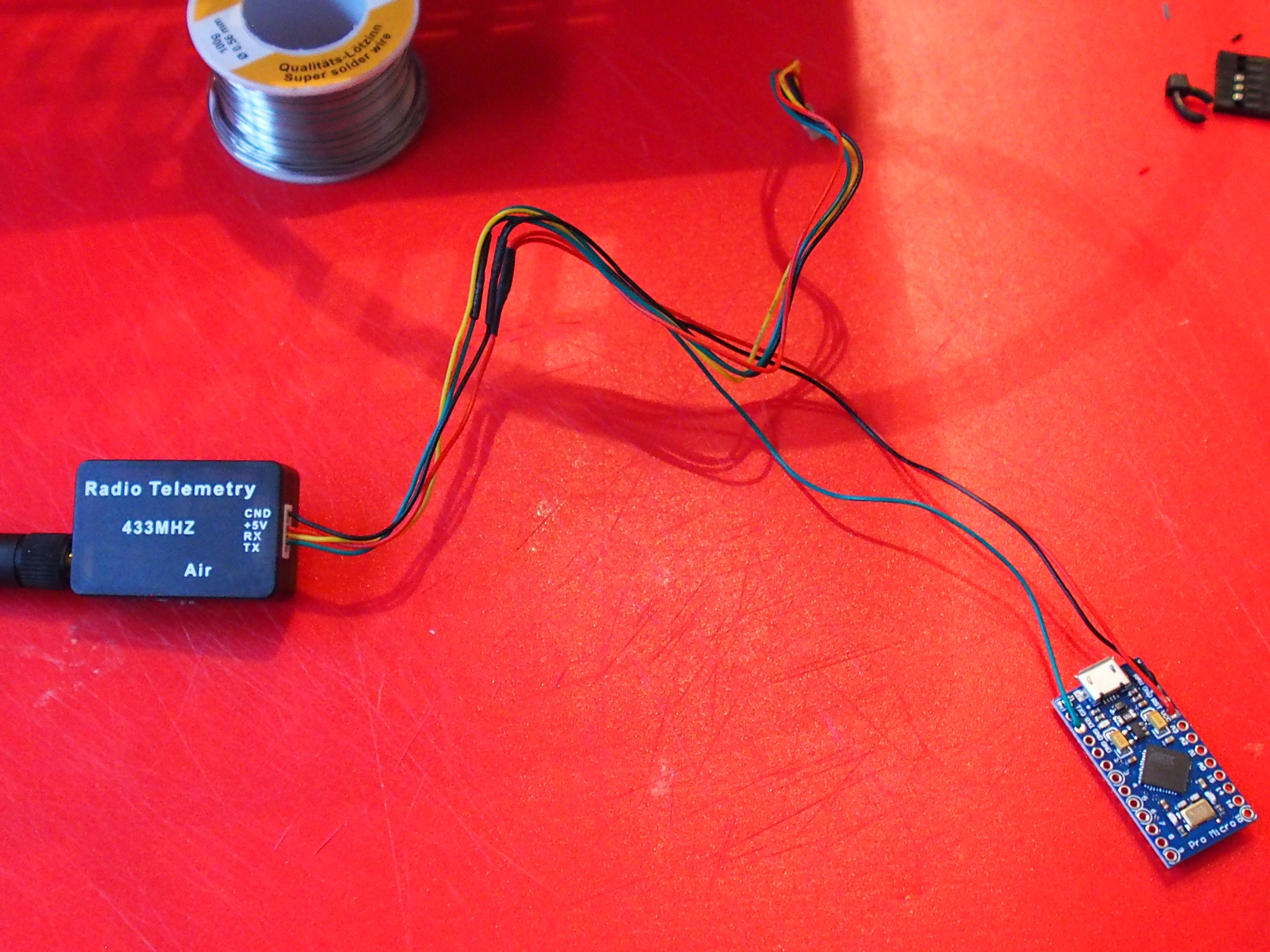
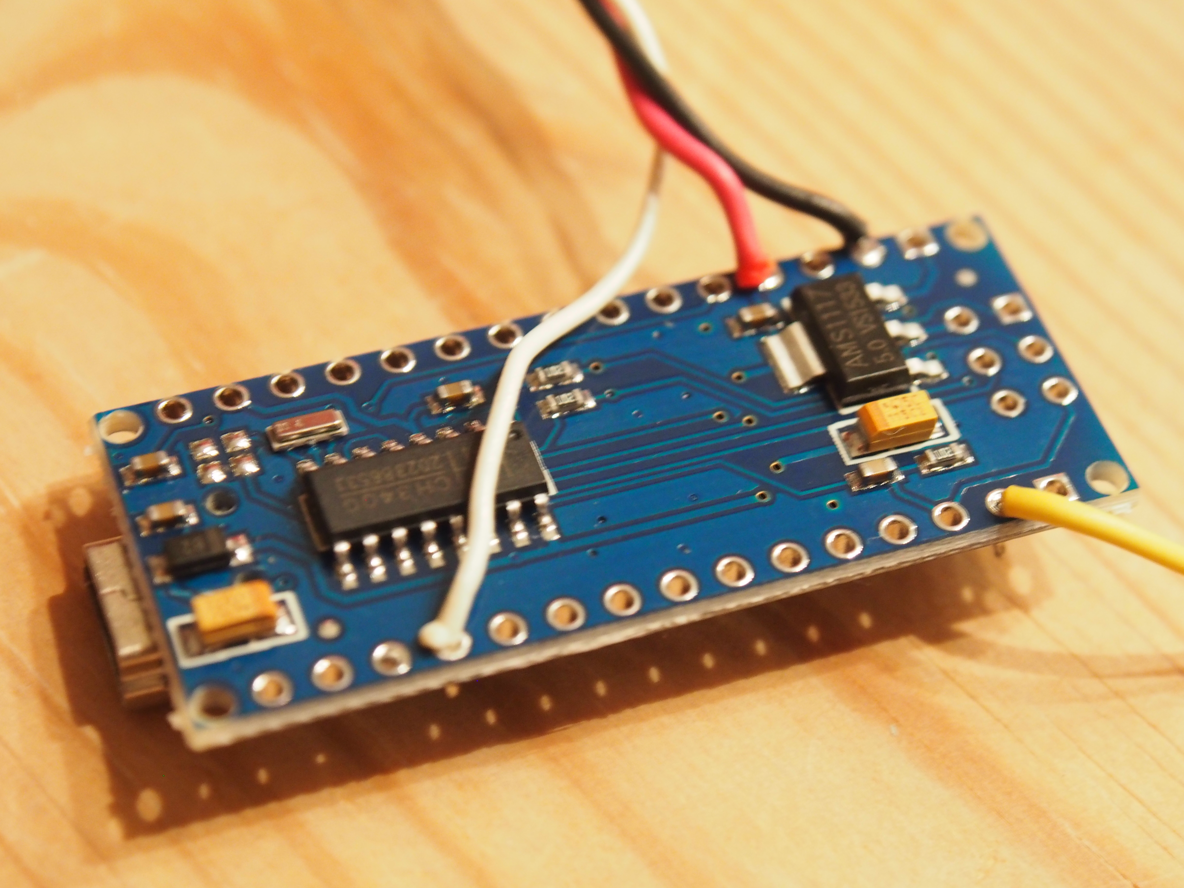
The translation between Naza-GPS and S.Port is done by an arduino nano which is connected to FrSky-S.Bus on Pin9 and to GPS Tx on Rx (also power from the receiver cable).
I used the software by Alezz in this thread but had to make some changes to get it running. My changed version is online at GitHub.

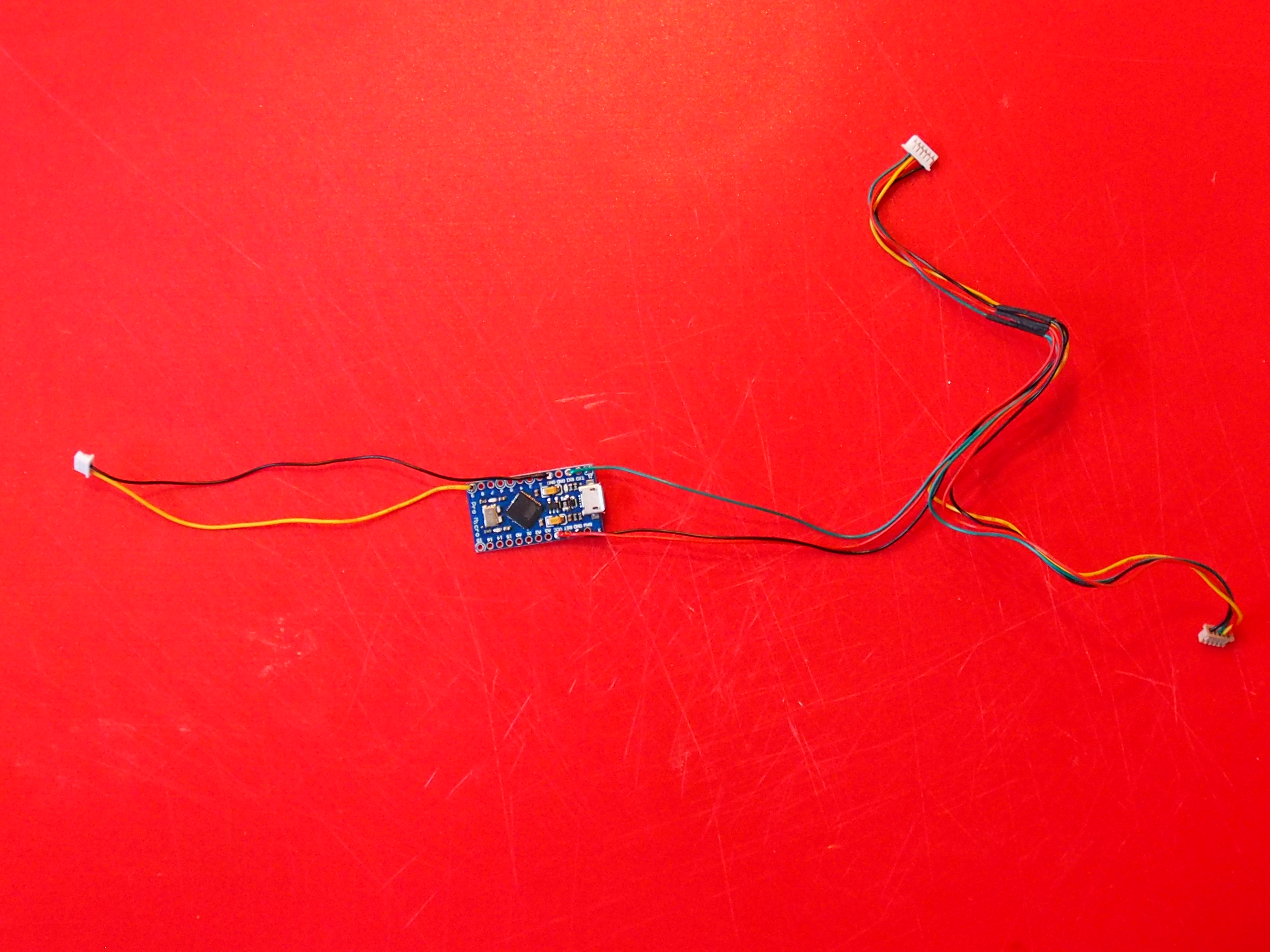
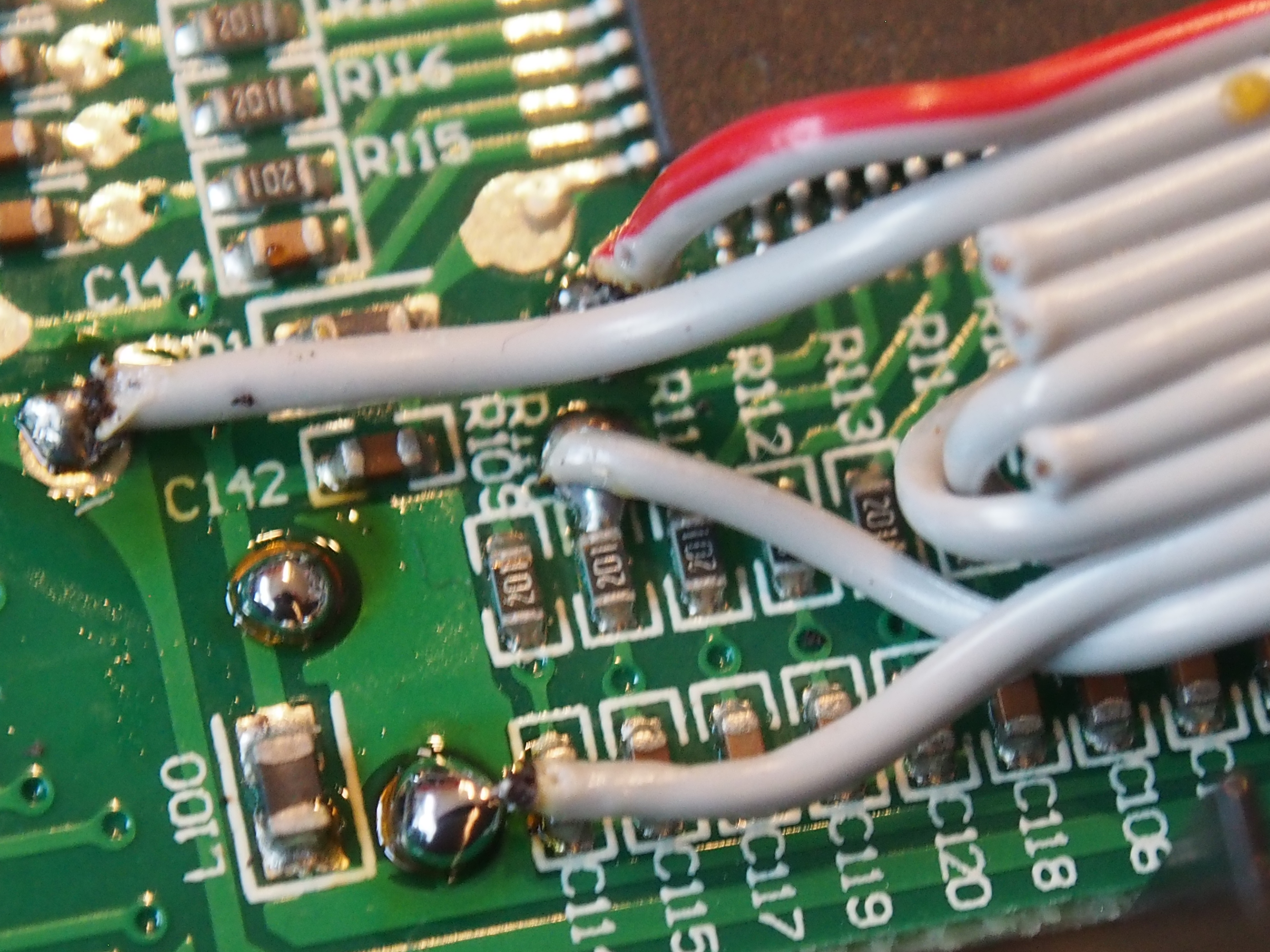
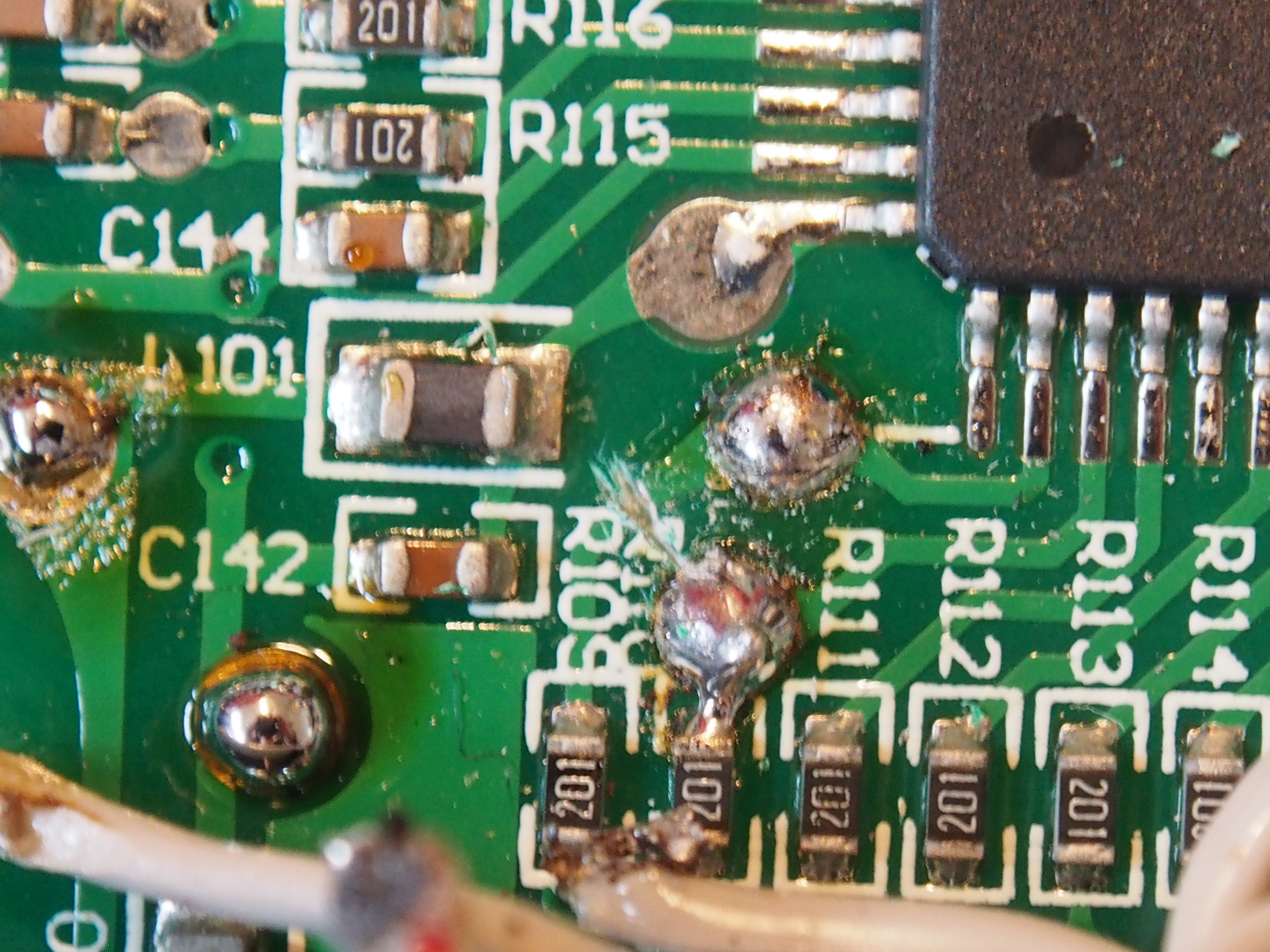
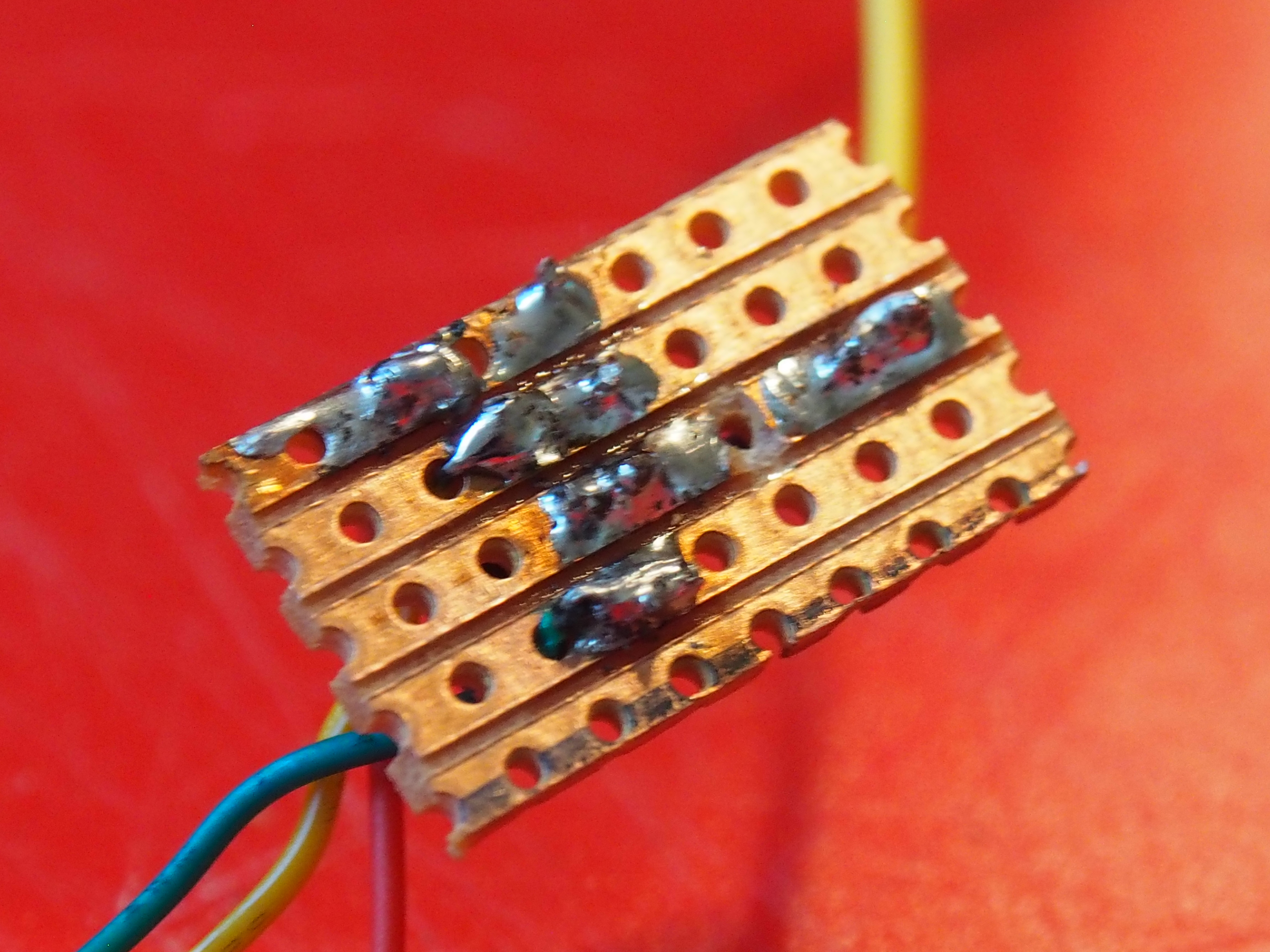
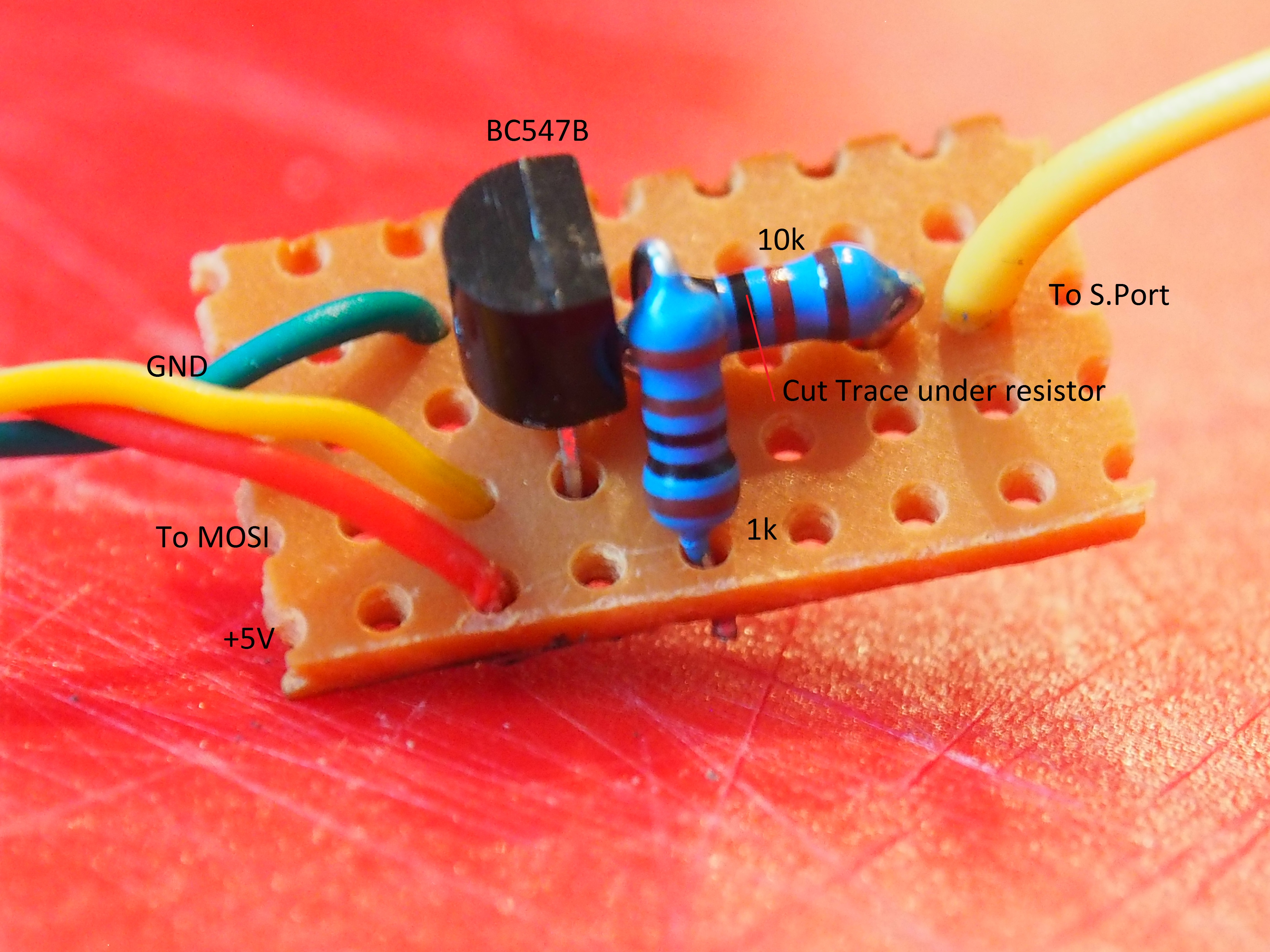
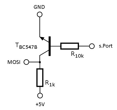
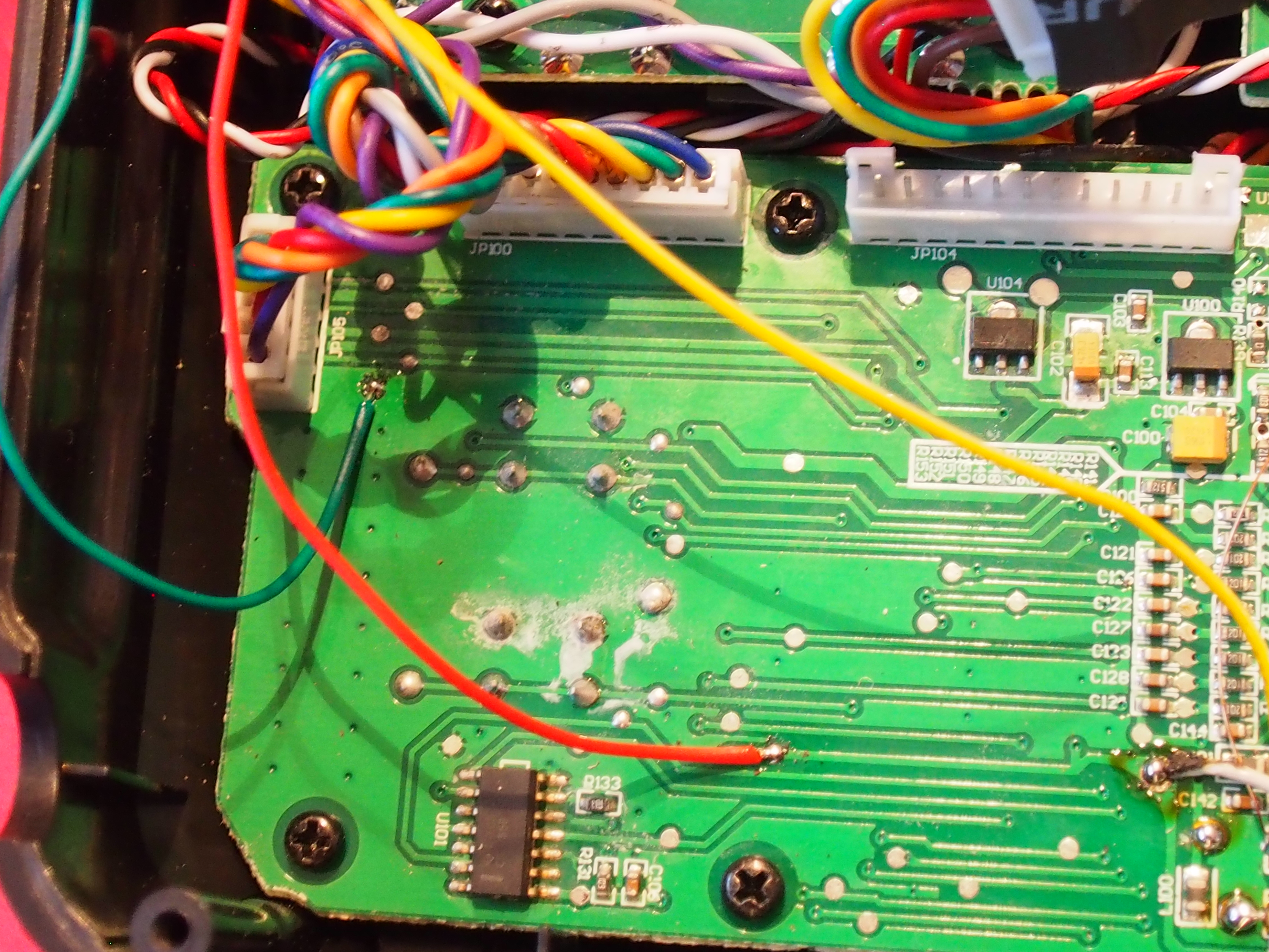
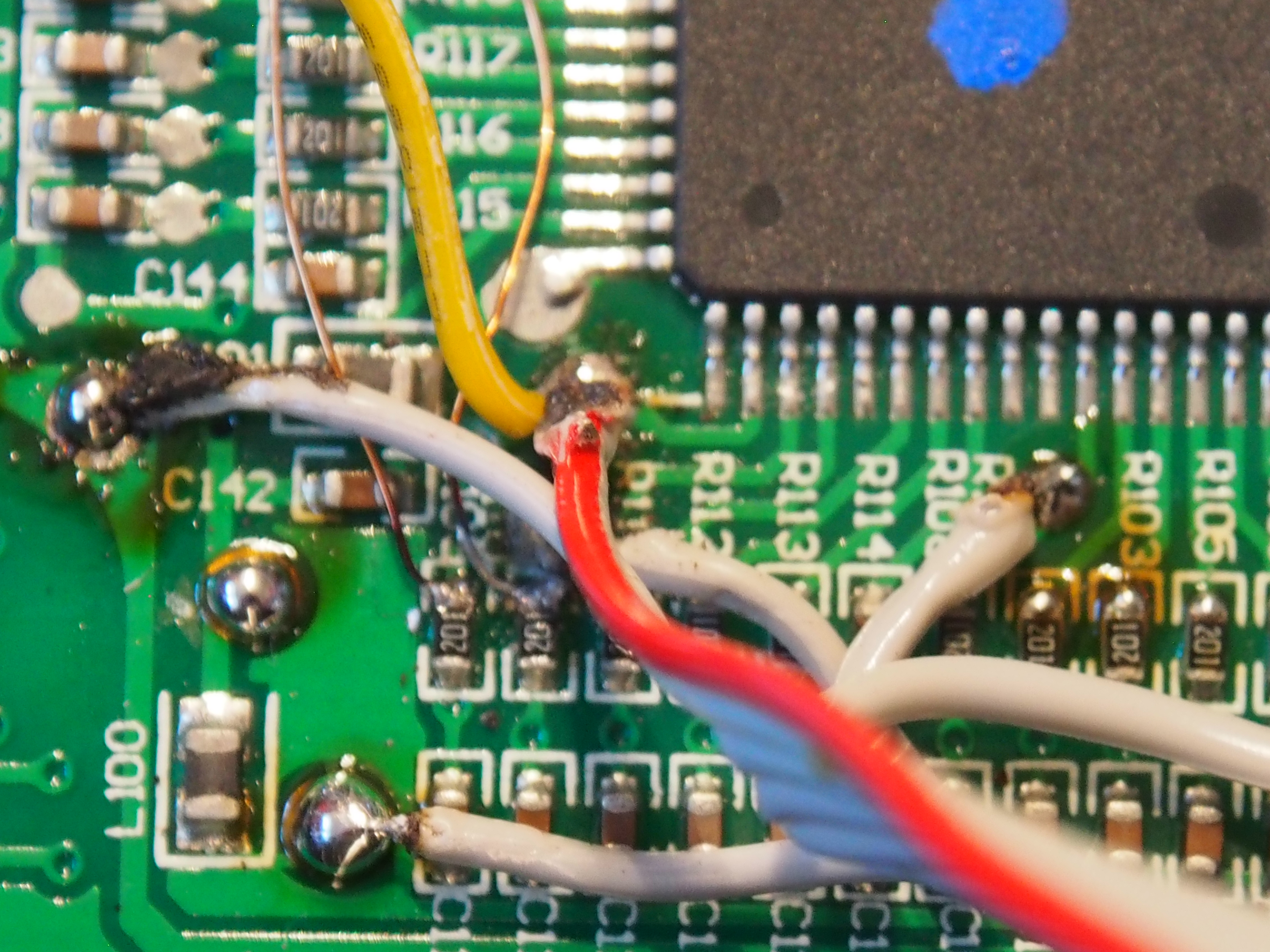
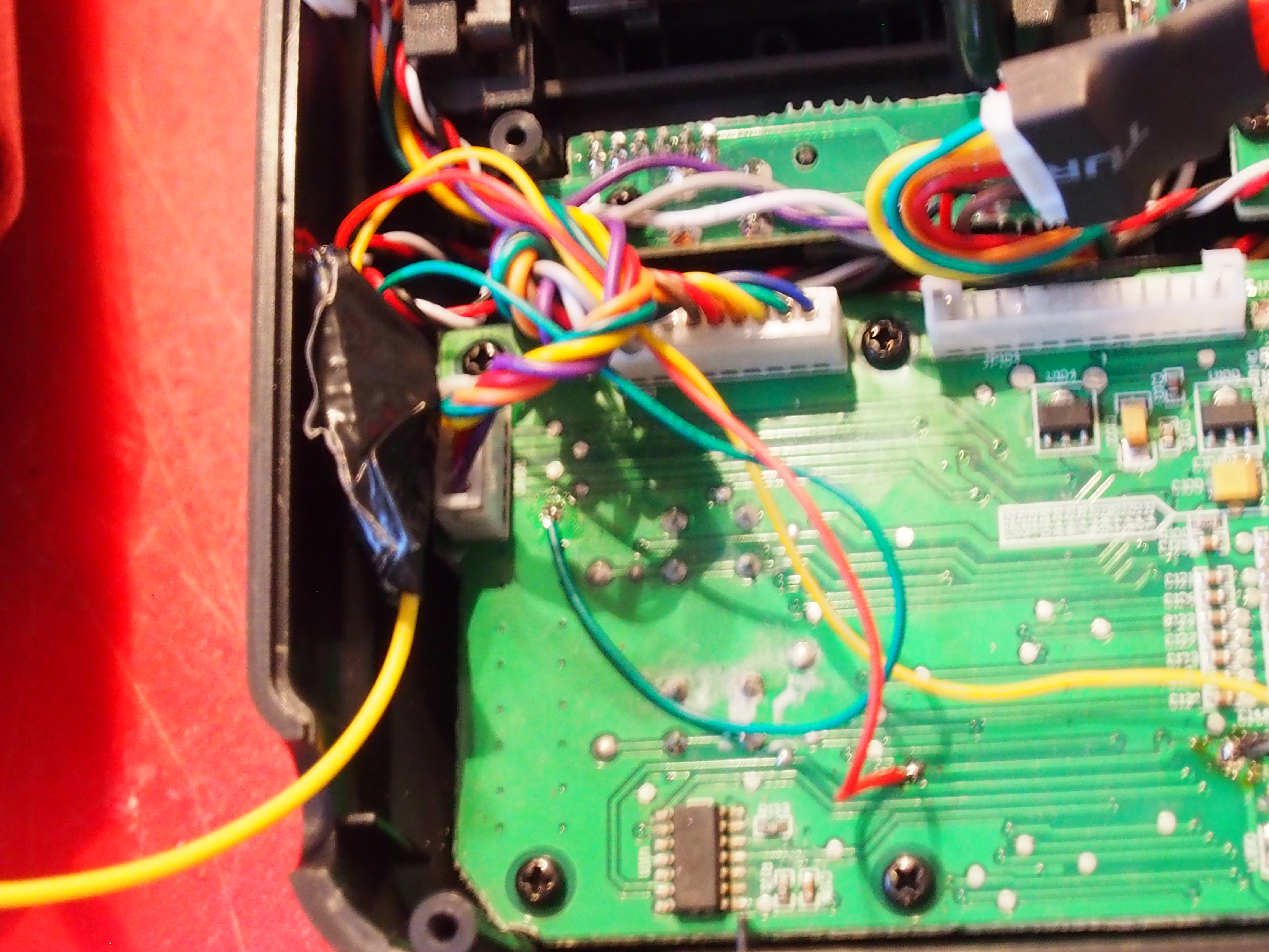
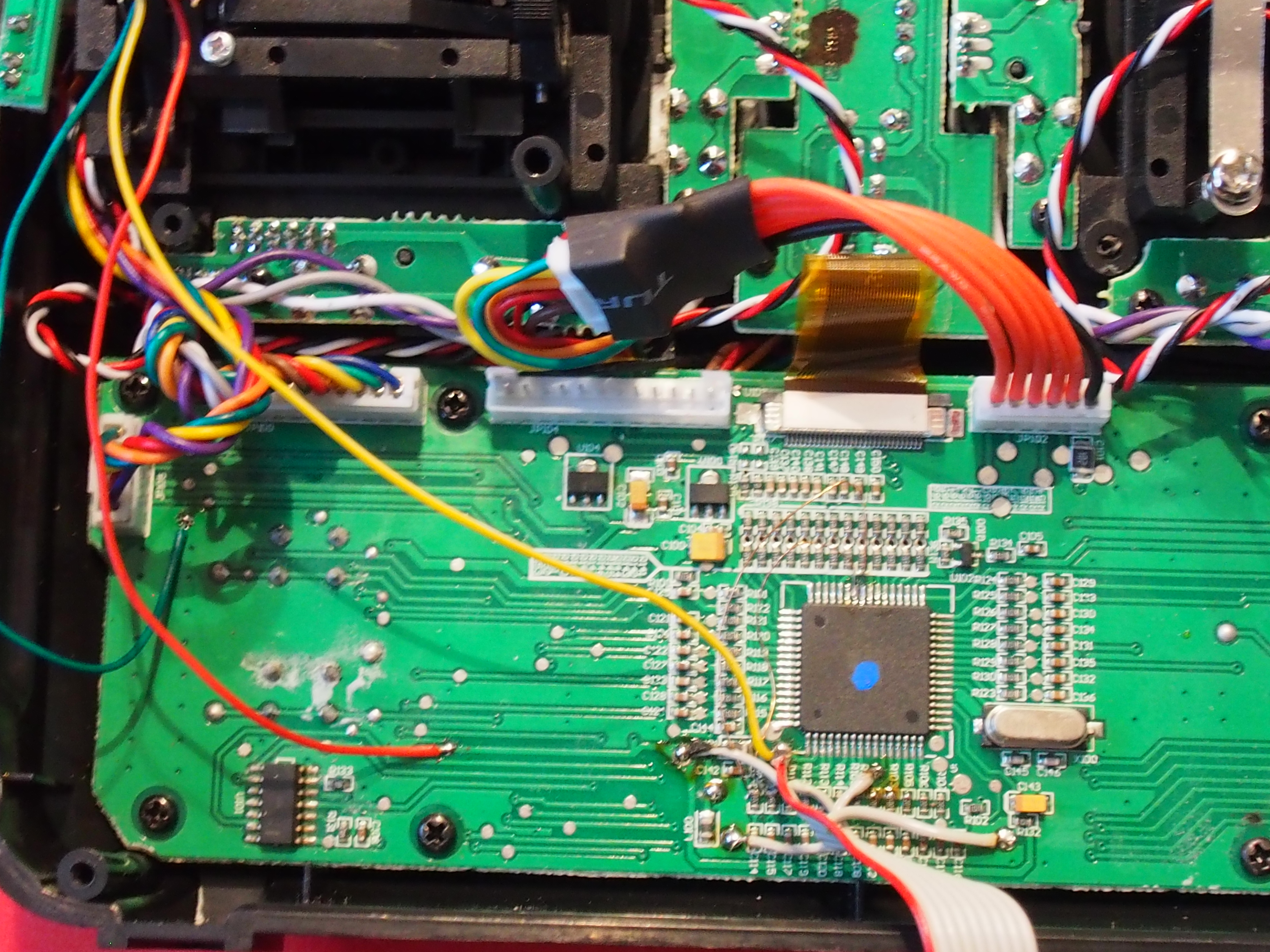
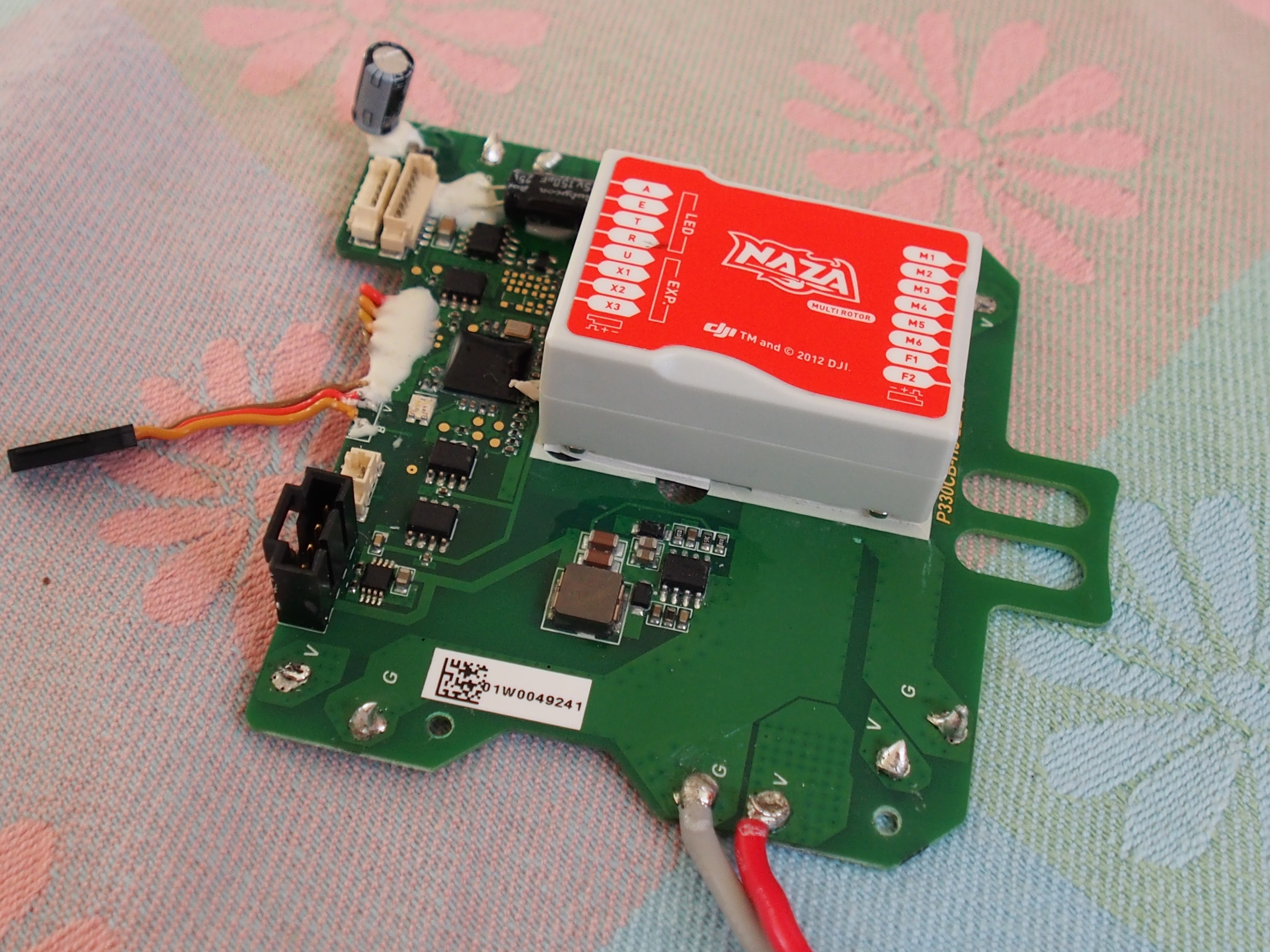
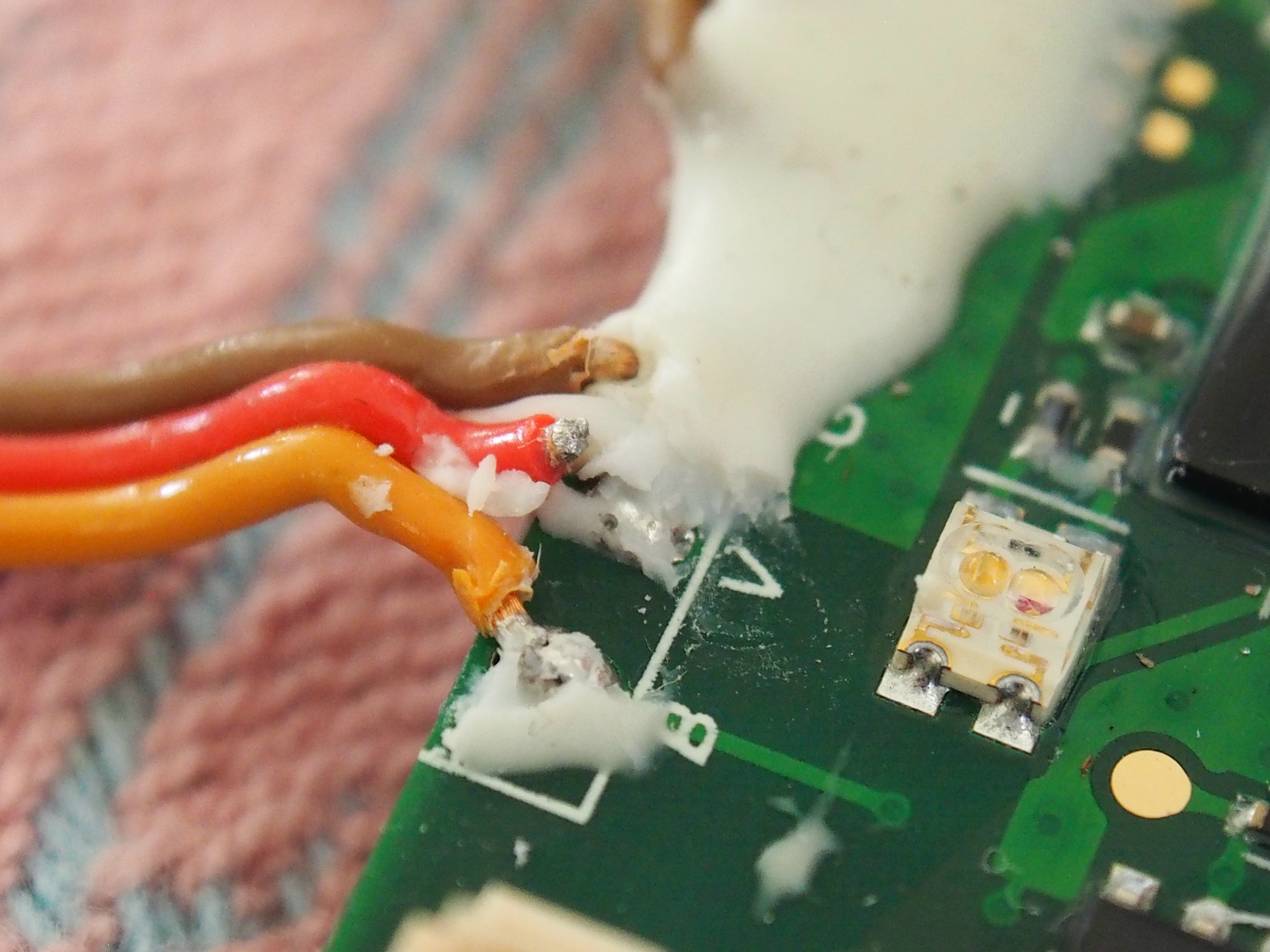
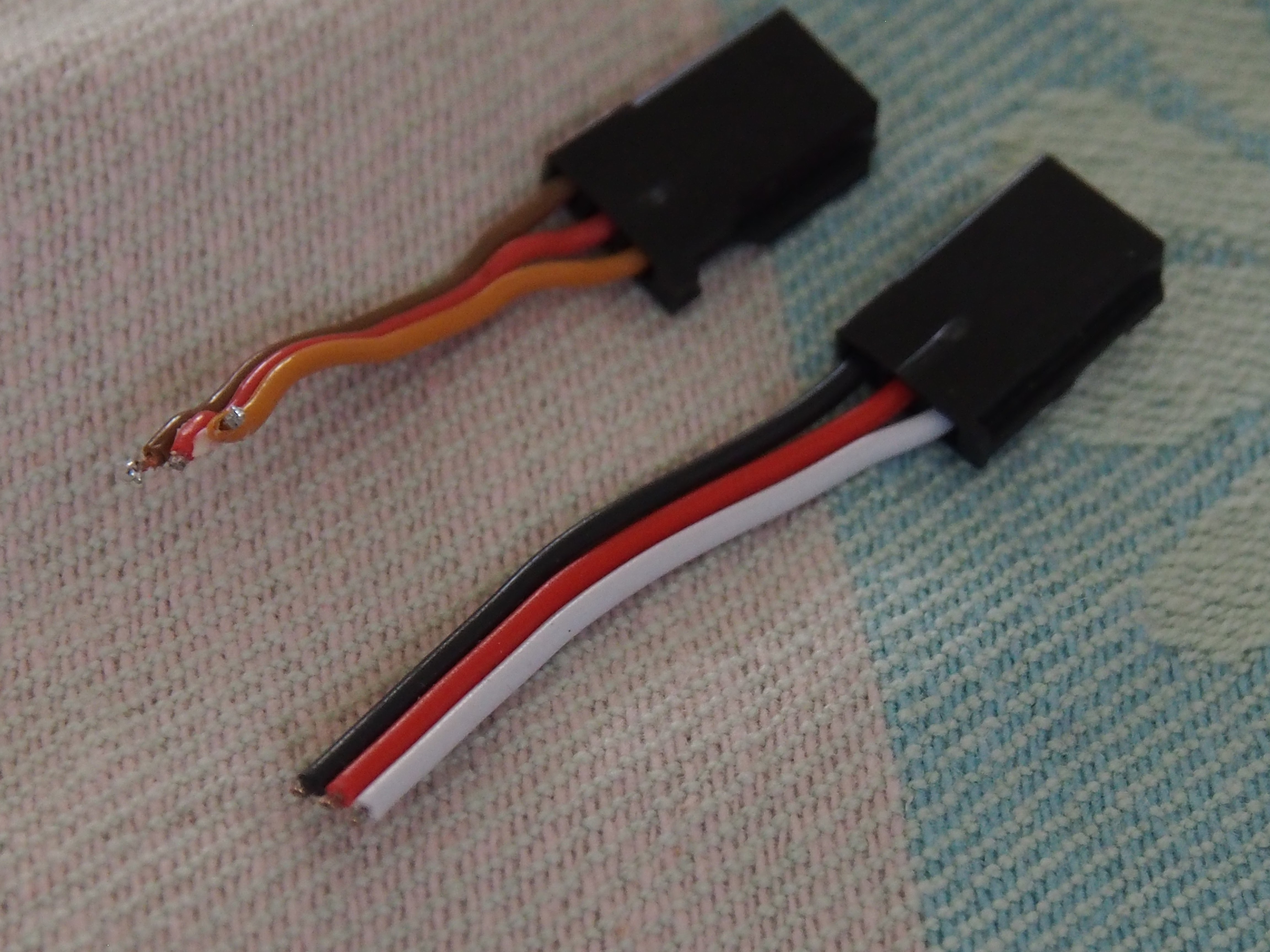
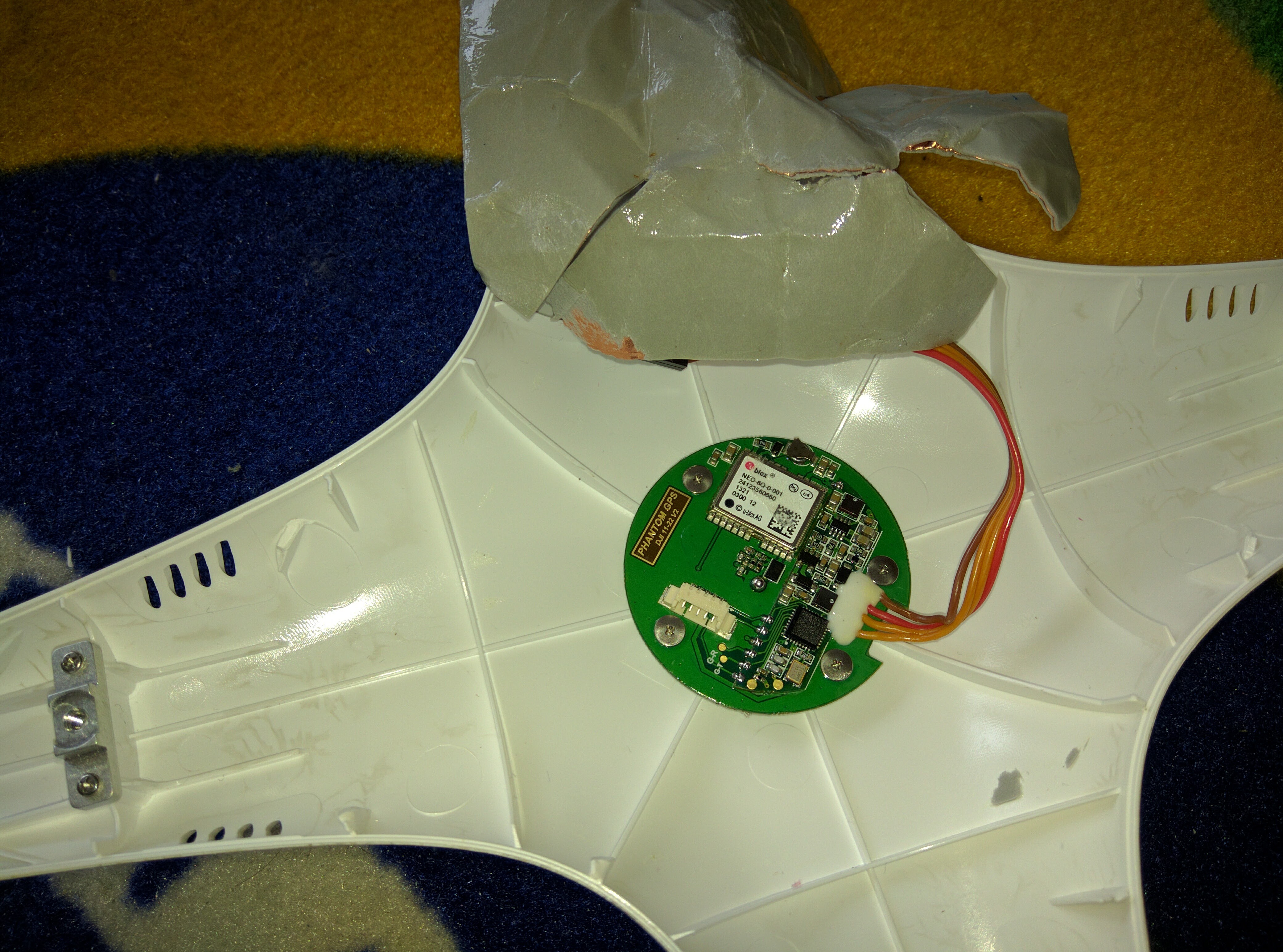
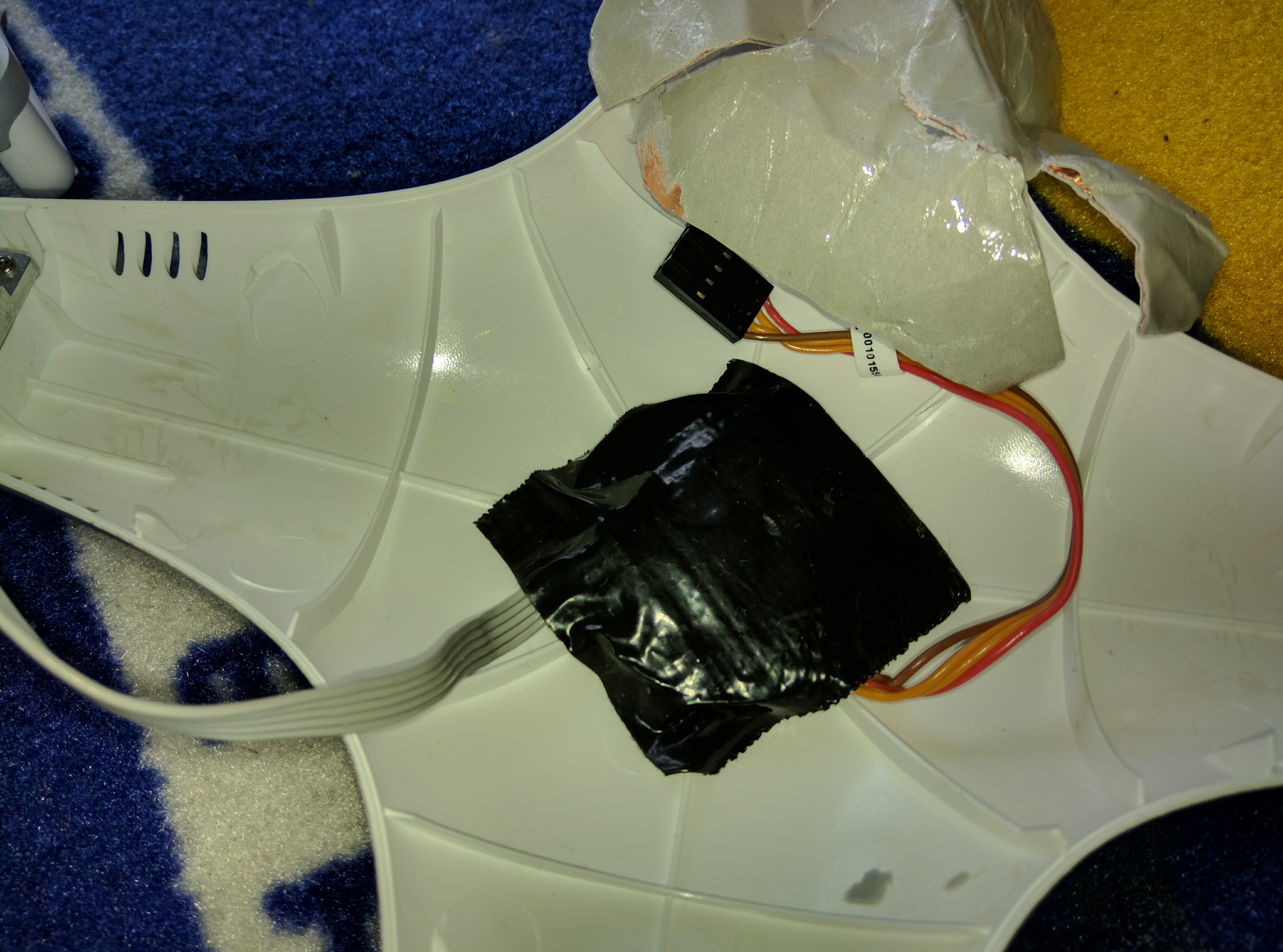
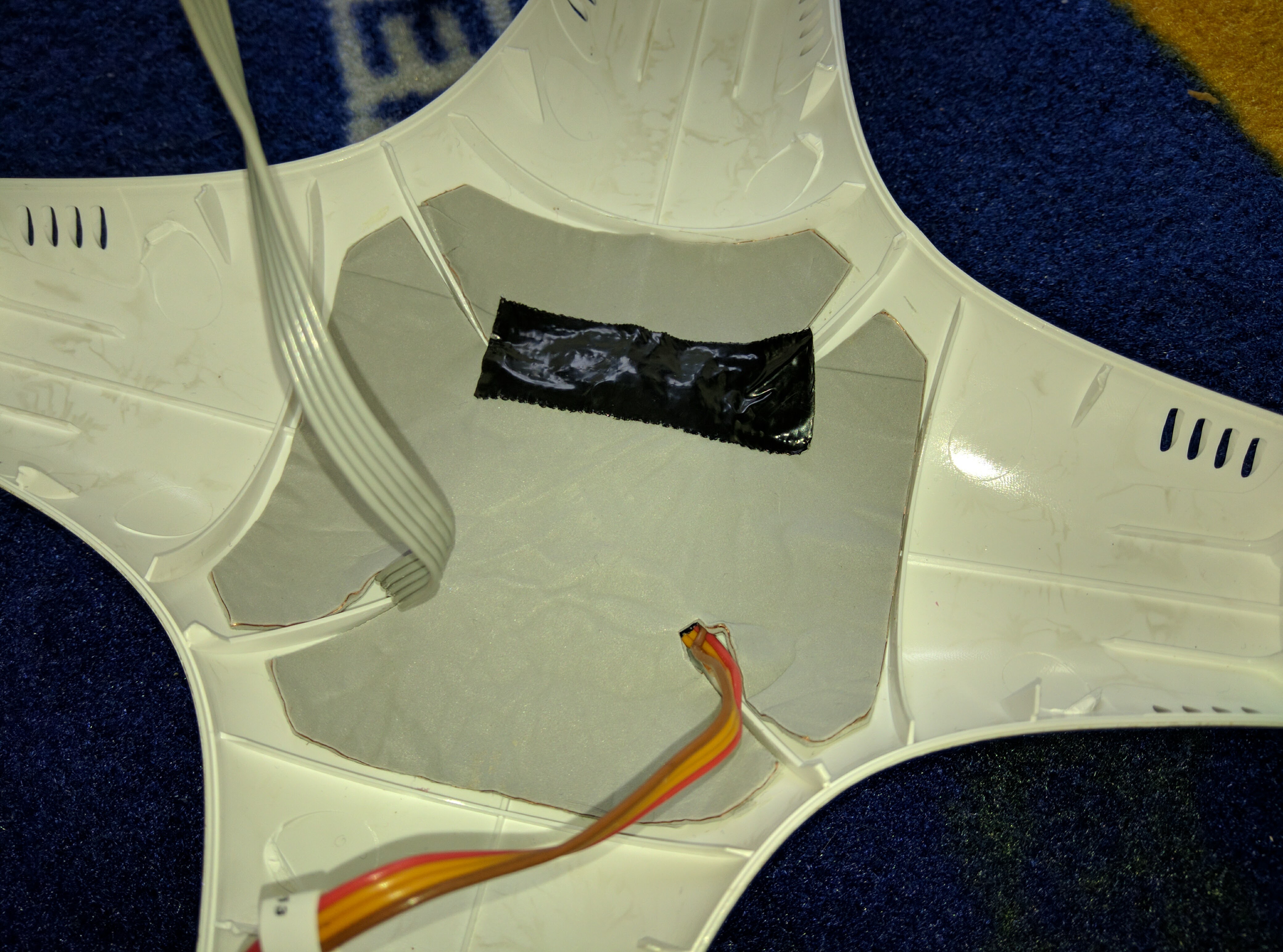
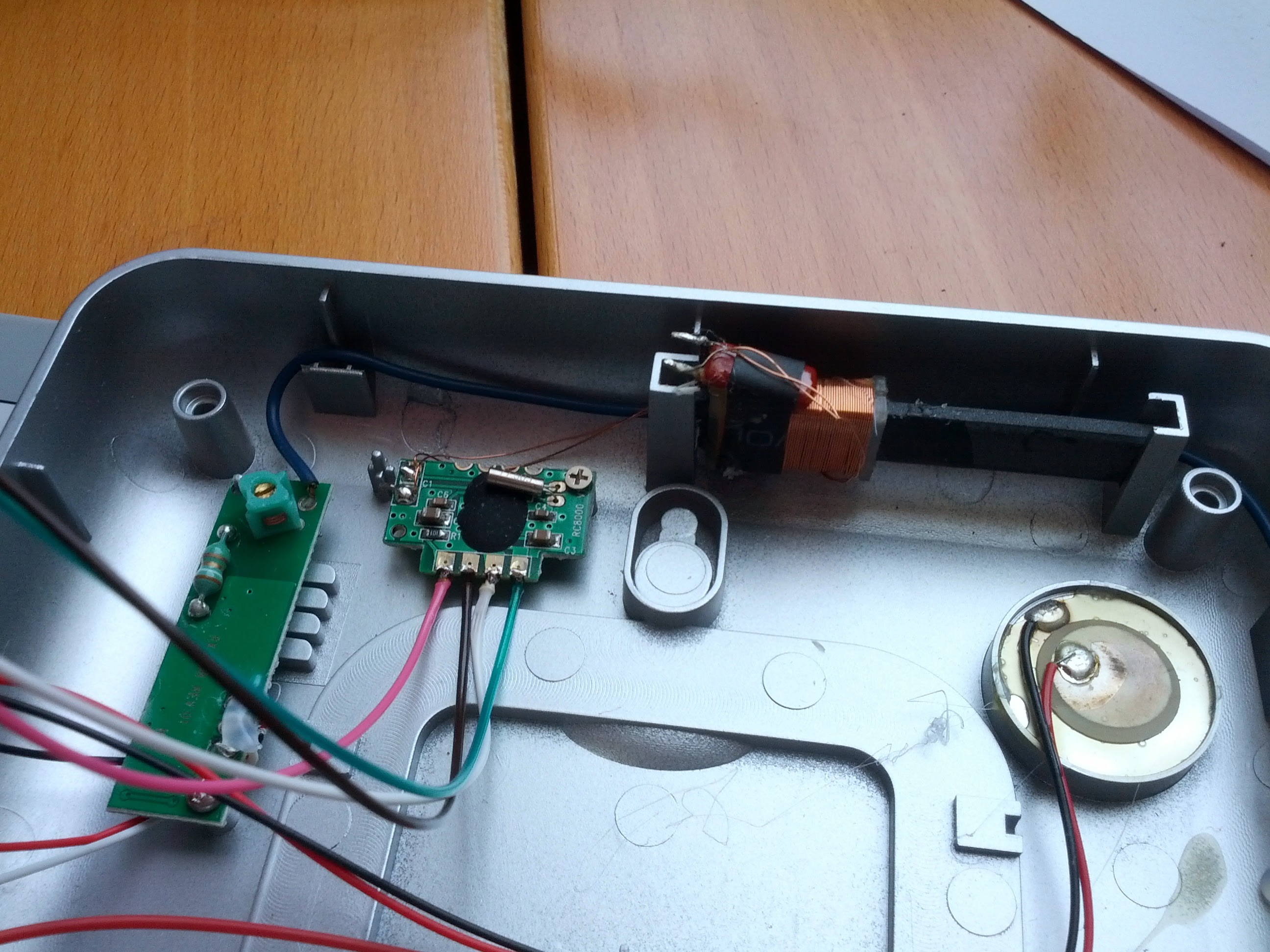
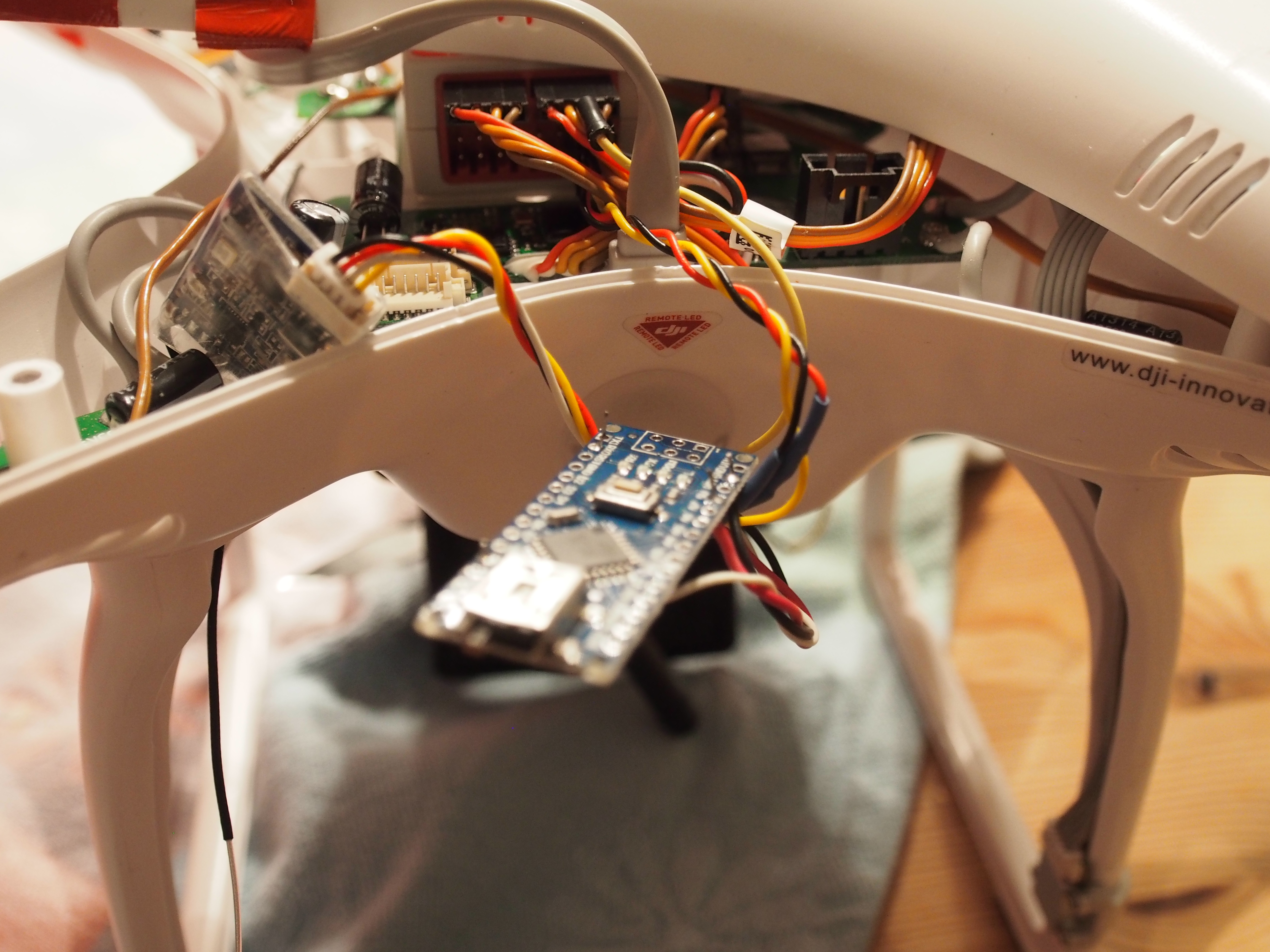
Here are some Pictures of the harness with the arduino and the Installation in the Phantom 1.

  • OLYMPUS DIGITAL CAMERA
  • OLYMPUS DIGITAL CAMERA
  • OLYMPUS DIGITAL CAMERA
  • OLYMPUS DIGITAL CAMERA
  • OLYMPUS DIGITAL CAMERA

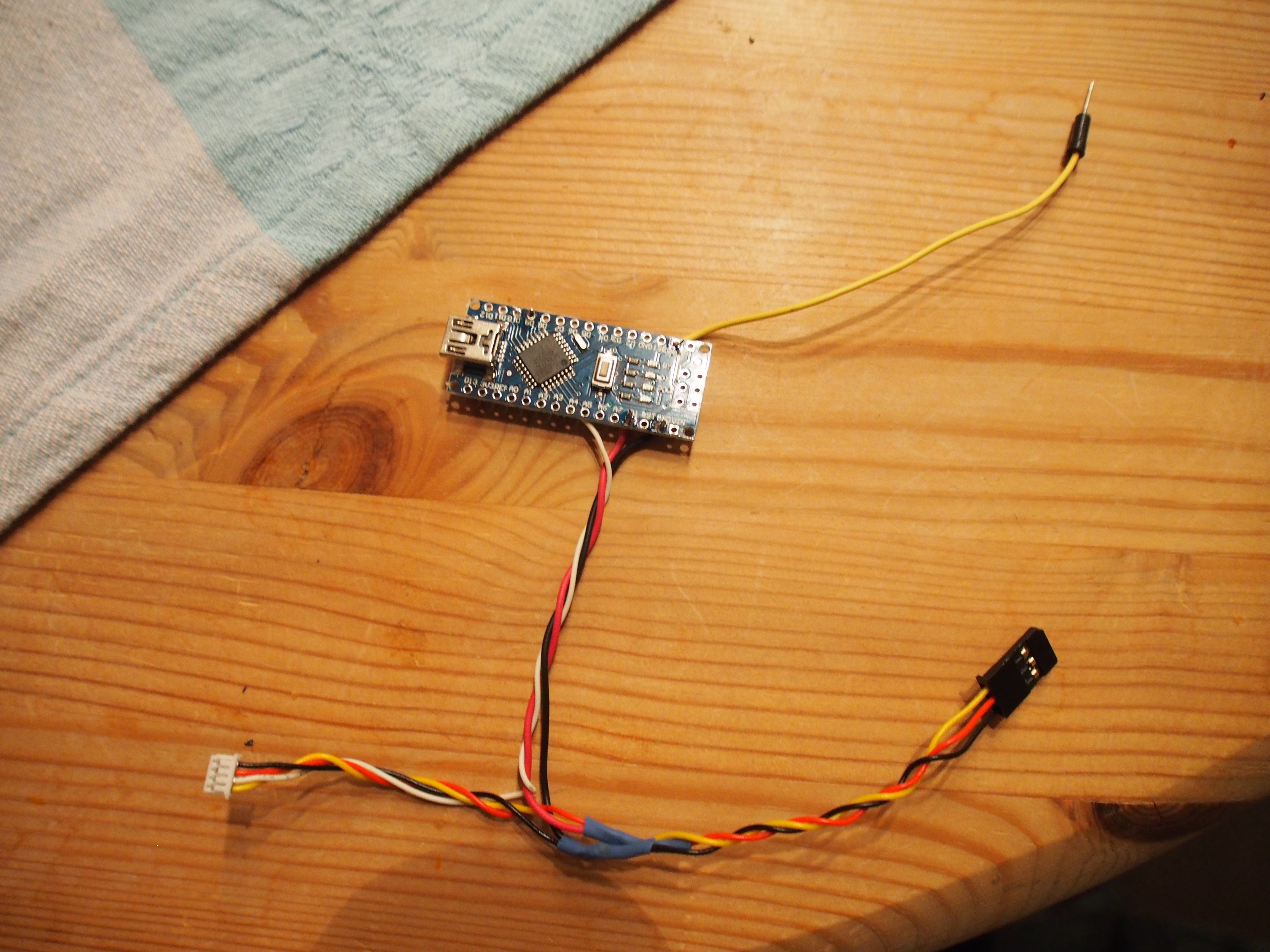
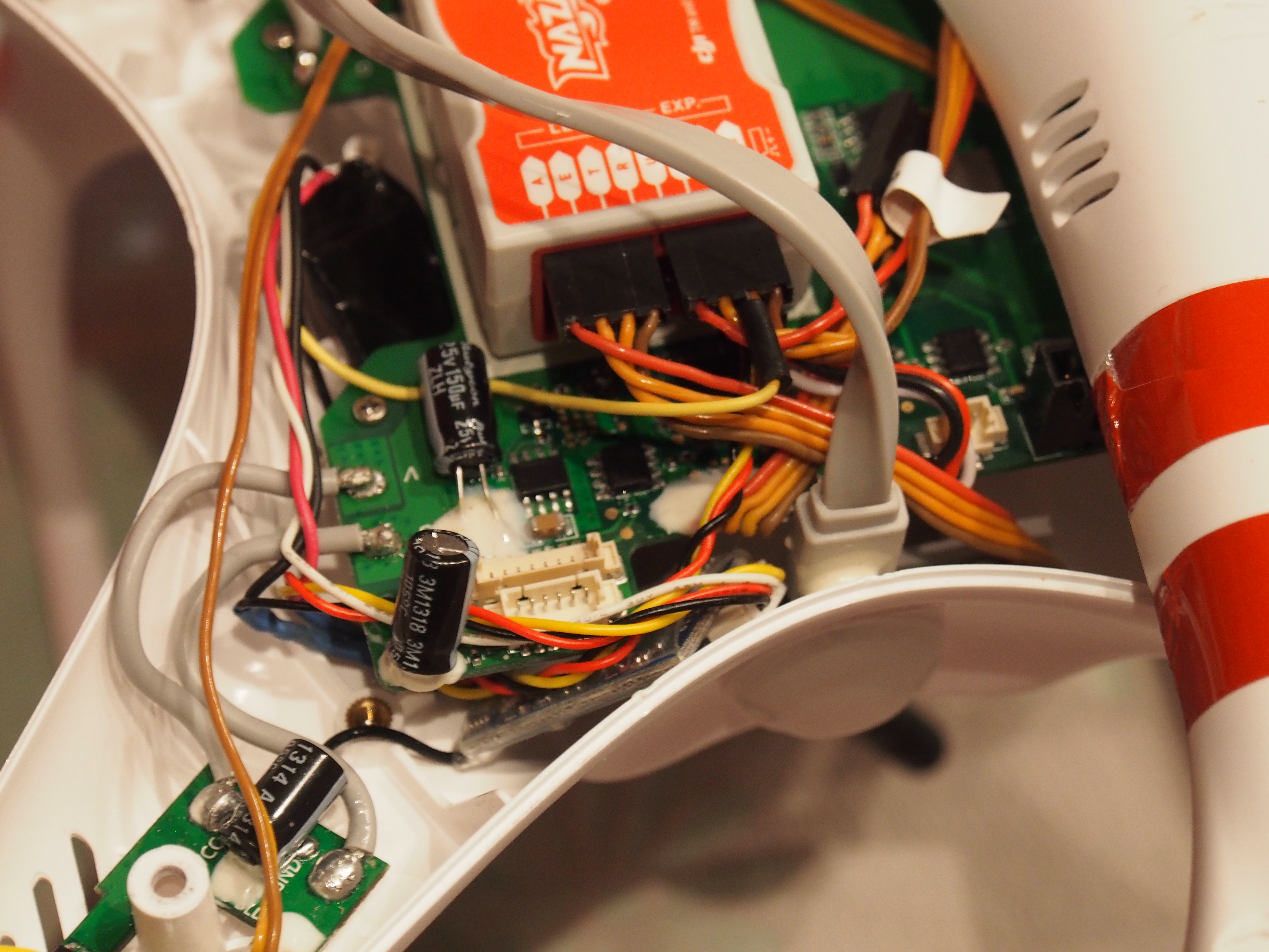
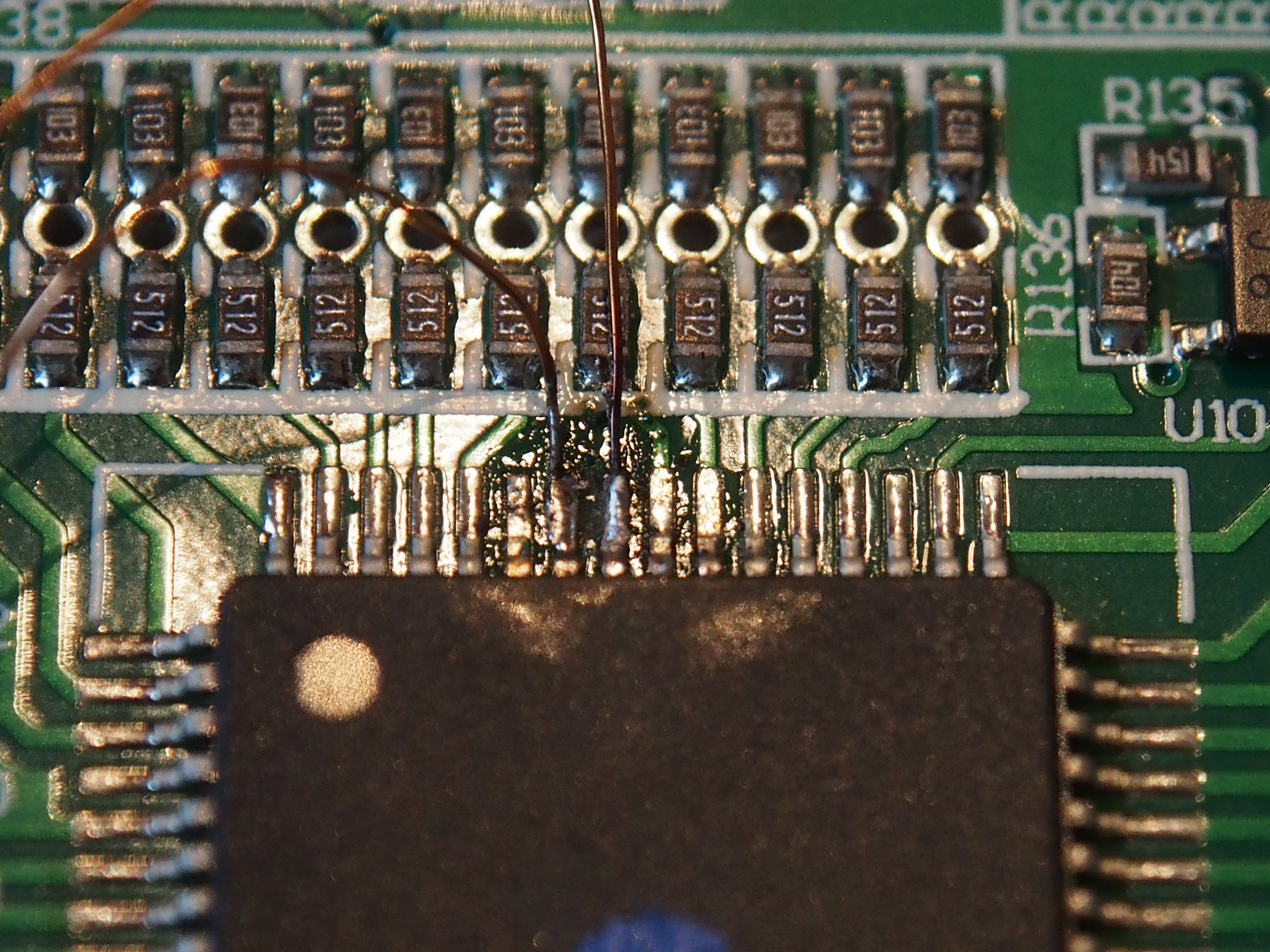
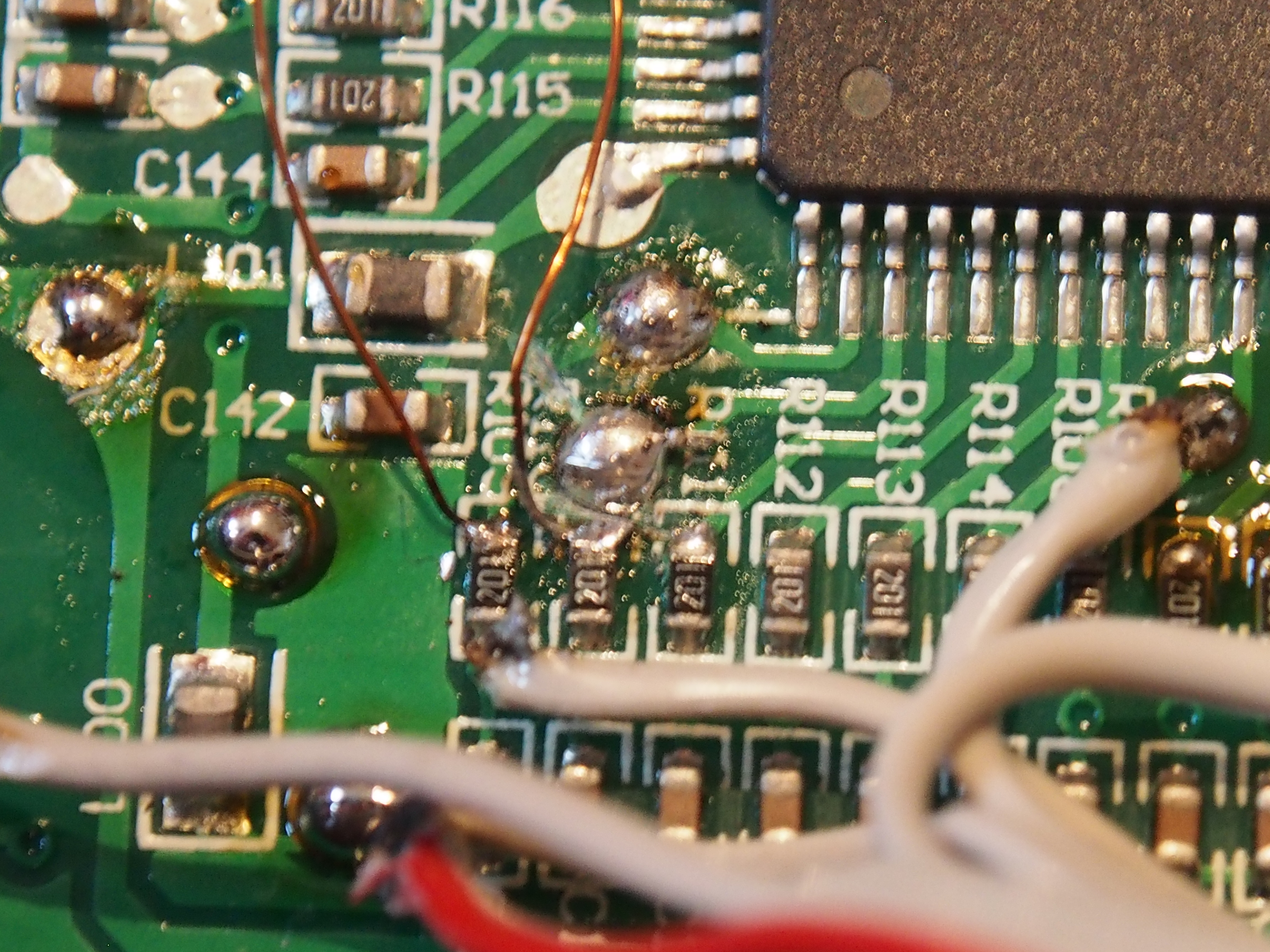
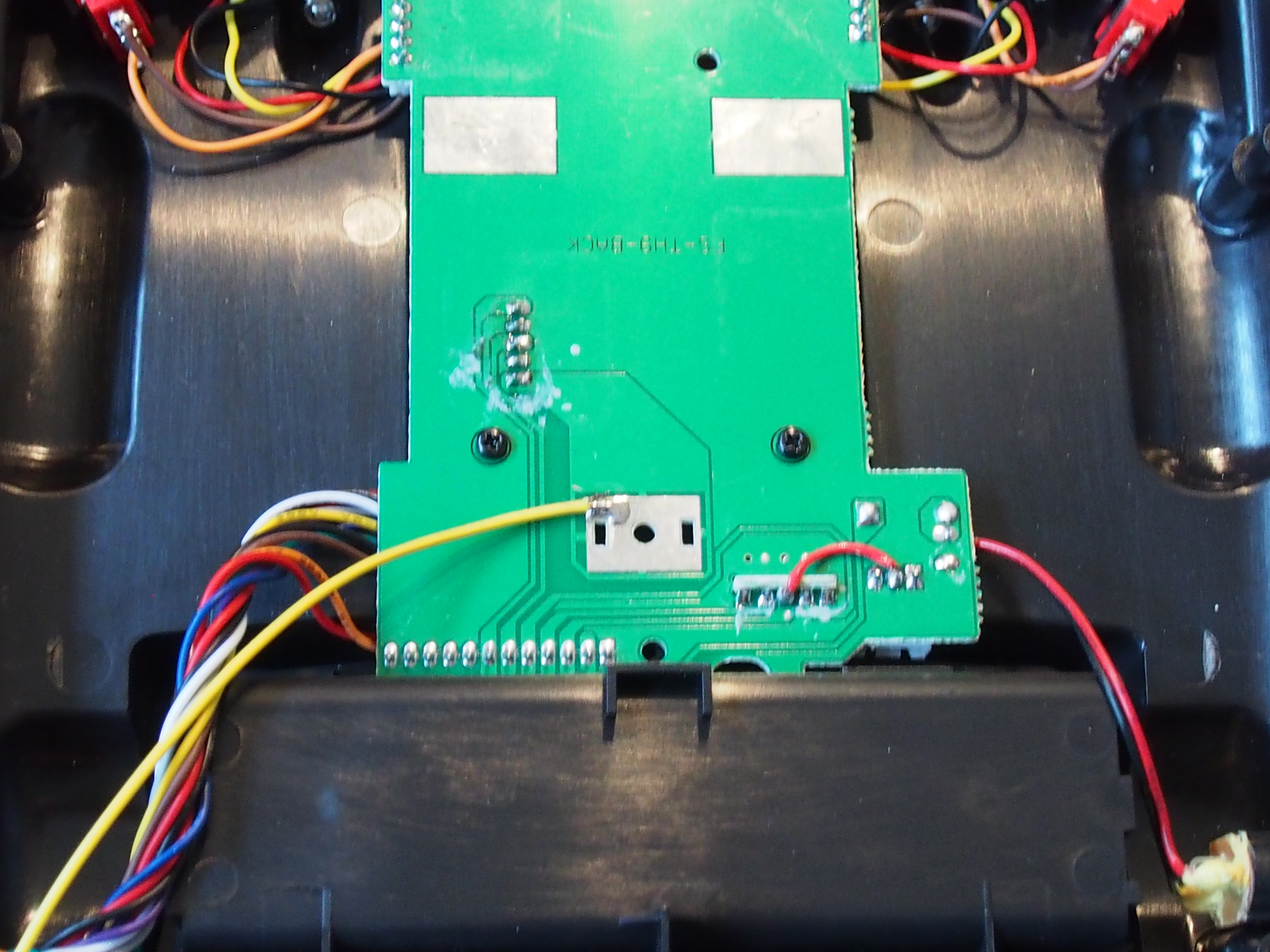
I didn’t want to cut the GPS connector, so I just pushed a jumper wire in the connector.
That was initially just for testing but made such a solid connection that this will stay in there.

  • OLYMPUS DIGITAL CAMERA
  • OLYMPUS DIGITAL CAMERA

The GPS Format in Degrees+Minutes formatted as DDMM.MMMM.
So 1234.5678 means 12°34.567′

I still have some trouble with the GPS coordinates, sometimes just the Longitude will be transmitted and Latitude is just 000 but this will be updated as soon as I get further.
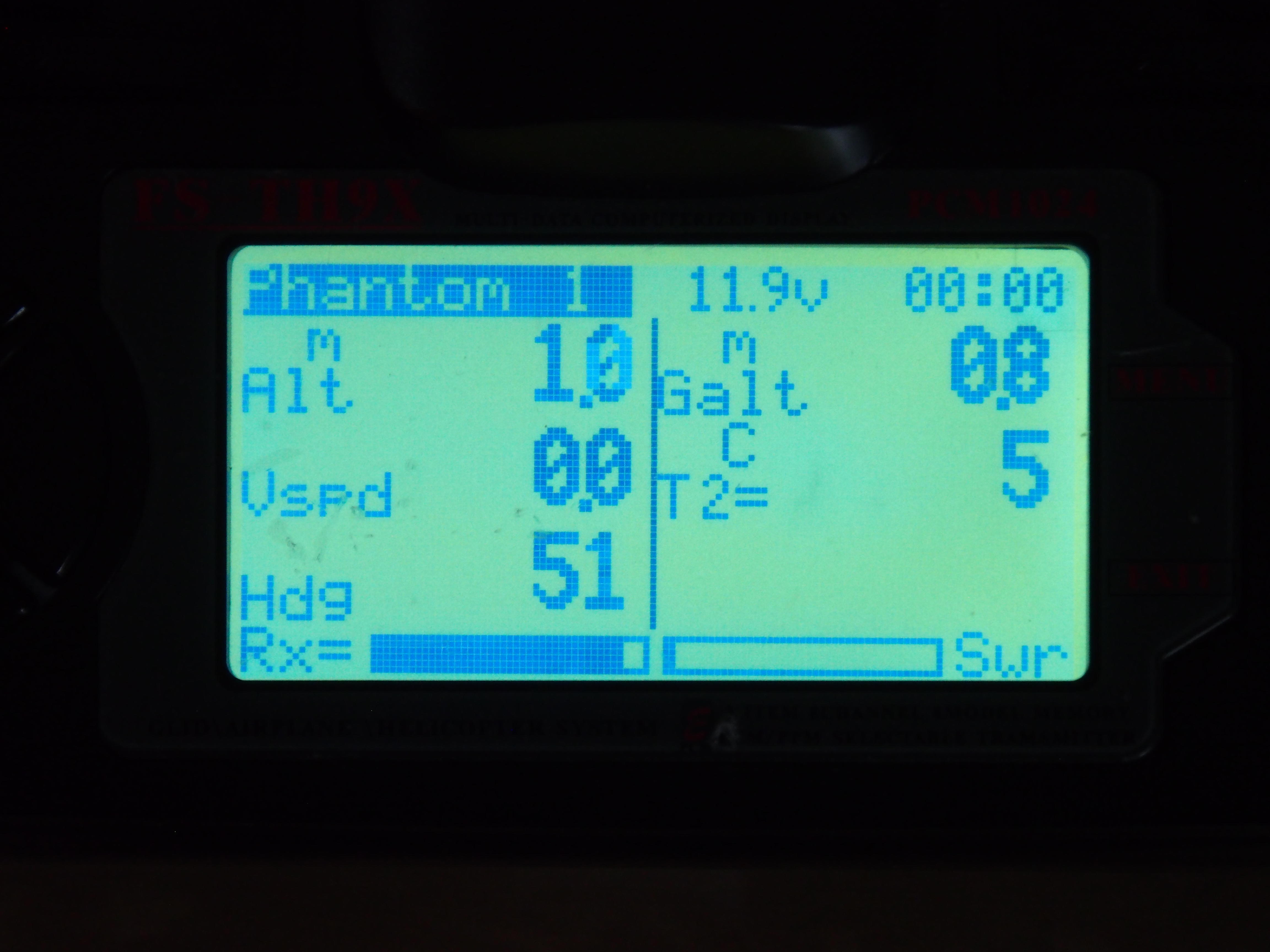
Also I’m a little confused about the “Alt” “Galt” and the “Alt” on the GPS screen. They all differ, but I will observe that during flight and remove the ones I won’t need from the arduino code.

Categories
Electronic upgrades Multicopter

Telemetry mod for APM and FrSyk X-Series (X4r)

After the Telemetry mod of the Turnigy 9x, the air-side has to be able to communicate, too.

Because the APM is not able to speak the FrSky-Protocol itself, a converter is needed to translate the data. There are several projects out there, mostly using a teensy. I decided to use rotcehdnih’s version, which is also cabable of running on an arduino nano or micro.

This is quite simple, just burn that softwre to an arduino (I’m going with an arduino pro micro), connect RX to the TX of the telemetry port and pin 9 to the S.Port of the FrSky receiver. Then just add some power (from the APM Telemetry port for example) and there you go!

  • OLYMPUS DIGITAL CAMERA
  • OLYMPUS DIGITAL CAMERA
  • OLYMPUS DIGITAL CAMERA
  • OLYMPUS DIGITAL CAMERA
  • OLYMPUS DIGITAL CAMERA
Categories
Electronic upgrades Multicopter

Telemetry mod for the Turnigy 9x an FrSky XJT Module

Hey Guys,

today I modded my Turnigy 9x to be able to receive Telemetry date via the FrSky XJT module.
There are many Telemetry mods for the 9x out there but most of them for the DJT or DHT module which use a serial connection on the ground side. The XJT also has a S.Port wich is already connected to the internal 5-pin connector. This makes any modification to the module unnecessary.

Like on the serial mod, you have to free up the UART pins on the 9x processor which are used by the two lower rear switches. In the images you can see that I did already connect the ISP Pins for flashing new Firmware to the 9x. Then I cut the traces for the most left resistors and connected them to the unused pins 41 and 42.
The two freed pins (RX) and (TX) are again getting connected to the ISP pin. Pin 2 will also be our S.Port pin.

  • OLYMPUS DIGITAL CAMERA
  • OLYMPUS DIGITAL CAMERA
  • OLYMPUS DIGITAL CAMERA
  • OLYMPUS DIGITAL CAMERA
  • OLYMPUS DIGITAL CAMERA

Important Note: Don’t do the mod like I did. Just desolder the two resistors and replace them with wired 120Ω one. So you don’t have to cut any traces and this makes soldering a lot easier.

Now we need to create a little circuit for inverting the S.Port signal (not quite sure if this is necessary, but it worked for me!):

  • OLYMPUS DIGITAL CAMERA
  • OLYMPUS DIGITAL CAMERA
  • OLYMPUS DIGITAL CAMERA
  • schematics

The S.Port is connected to pin 5 of the internal connector between the 9x and the module. This pin is unused and connected to the large solderpad. (Don’t know what it was supposed to be). I just connected the signal cable to the large solder pad.

  • OLYMPUS DIGITAL CAMERA
  • OLYMPUS DIGITAL CAMERA

Now the inverter PCB hast to be connected to the processor. Signal to MOSI, power to 5V and GND to GND:

  • OLYMPUS DIGITAL CAMERA
  • OLYMPUS DIGITAL CAMERA
  • OLYMPUS DIGITAL CAMERA
  • OLYMPUS DIGITAL CAMERA

I also wrapped the PCB in duct tape to insulate it.


That’s the hardware side.

I used the er9x Firmware in the FrSky version wich uses the changed switch pins and enables telemetry. You can download the firmware and the flashing utility from the er9x webside. Remember to save / write down your settings before flashing.
To get the 9x to listen to S.Port instead of RX/TX, you have to set the protocol to PXX. Now you should already be able to see the RSSI values.

REMEMBER to rebind the receiver if you switched from another protocol to PPX.

Categories
Multicopter

Repairing an old broken DJI Phantom

I recently bought a cheap broken DJI Phantom 1 and would like to show you the process of analyzing and repairing the drone.

There were multiple problems, I will explain them one by one.

1. Phantom drops down when tilting

Problem

Here you can see that the phantom is hovering quite nice, but in the forward flight it suddenly falls down, all LEDs went off.

Cause

The Phantom has an internal USB cable which is connected to the microUSB port of the LED-module. This cable usually is hold in place by a cable tie and is accessible by the battery door.
In this phantom, someone removed that cable tie and the cable was flying around loosely, causing a short on the solder points of the battery connector or the power line for the speed controllers.

Solution

Fixed the cable with a cable tie. – Easy one…

2. Copter falls again midair

Problem

The Copter falls down while hovering, all LEDs stays on and starts beeping.

Cause

  • OLYMPUS DIGITAL CAMERA
  • OLYMPUS DIGITAL CAMERA

The X3 connector from the PMU-board to the Naza is the power source for the flight controller. The red wire is the +5V line which has a loose connection on the board, although covered in the white protective glue.

Solution

I simply replaced the cable with a new one…

  • OLYMPUS DIGITAL CAMERA
  • OLYMPUS DIGITAL CAMERA

Easy to fix, hard to find.

3. Copter wobbels in ATTI mode – (really easy one)

Problem

When flying in ATTI-mode (Stabilized, without GPS), the copter starts to shake and wobble.

Cause

The previous owner changed the default board with the PMU-One for a zenmuse gimbal. The Naza (which contains the gyro sensors) is usually glued to the board with foam pads.
In this case, it was glued with superglue, wich won’t adhere to the coated PCB. So the Naza became loose and was just hold by the cables. I was impressed how stable it stays with this in GPS mode!

Solution

Fixed the Naza with foam tape.

4. Phantom randomly switches from GPS to ATTI mode

Problem

During a GPS flight, the LED randomly turns yellow for a few seconds and the copter starts drifting which means that it switched to ATTI mode.

Cause

  • img_20161015_145426
  • img_20161015_145531
  • img_20161015_145840

In the upper shell of the phantom is the GPS module which contains the antenna. To reduce interferences from the regulators, it is shielded with a rubber coated copper foil.
This foil was lacerated and the the copper foil wasn’t insulated on some parts. These touched the GPS module and randomly caused it to fail.

Solution

Just added some duct tape as insulation between the module and the copper foil.

Now, it seems to fly very stable and reliable. There are already further modifications queued…

Categories
Electronic upgrades

Retrofit radio controlled clock

Last sunday, germany switches to the daylight saving time again, so i needed to adjust some clocks.

We had a weathers station with wireless temperature and humidity sensors that has a clock which needs to be adjusted manuall while most of that weather stations have radio controlled clocks integrated.
Even my very cheap weather receiver which i got from a giveway and was only used to analyze the wireless temperature signal has a time receiver.

So i wondered if it is possible to put the receiver from the cheap weather station in the one we are using. Quickly opened it and found four empty soldering pads labled “RCC” – maybe radio controlled clock or something like that. Also the four pads itself are labled:

GND – Ground
VDD – Voltage source (3V)
PON – Power on Signal (3V)
TCO – TimeCOntrol? At least a data pin..

The labeling matches with the sensor, so i simply connected it:

  • IMG_20140330_140224
  • IMG_20140330_140237
  • IMG_20140330_140904
  • IMG_20140330_140207
  • IMG_20140330_140216
  • IMG_20140330_141438

Near the connector are two soldering Jumpers (S1 and S2) which are explained on the PCB and must be switched from S1 to S2.
Also there are two empty component places, usually used for the receiver which doesn’t exist on the source PCB:

R16: Pull-down resistor for the PON signal. This is already implemented in the receiver module
C12: Filter capacitor for the data signal – maybe not needed.

So both stay empty.

The case has already mounts for the antenna where my antenna exactly fits in!

At least everything is put back together and six minutes later:

  • IMG_20140331_105247

The time is synced! And again one less clock to adjust!