Categories
CAN-BUS Car mediacenter

Project MPi3 – New housing and published all source code

Previous: Display additional data


Hey there, I finally managed to upload source files for my Project!

Program at GitHub

Housing at thingiverse

The program currently listens for the previously mentioned diagnostic data. The Requests are send outside the program. I will change that when i figure out how to get the data without activly asking for them. Just by observing the bus.

  • In
  • Bottom
  • IMG_20151106_174410
  • IMG_20151106_175827
  • IMG_20151106_175846
  • IMG_20151106_180004
  • IMG_20151107_121508
  • IMG_20151107_121432

As you can see above, there is also a housing for the raspberry and the other components. The system is now installed hidden in my car, directly connected to the entertainment bus and the aux-in of the headunit.

The Connection is made with a 15-pin d-sub connector as follows:

MPi3

The audio in connects to the audio out of my tv receiver, the 12V are from the power source for the interrior lighting. This line will be activated when the car gets unlocked and stays active for about 30 minutes after locking the car. So the components won’t stay active all the time and drain my battery but will be available as soon as I enter the car.

  • IMG_20151107_113557
  • IMG_20151107_113642
  • IMG_20151107_130826
  • IMG_20151107_095606

My 12V USB adapter has two USB-ports. One was dissoldered and connected directly to the raspberry solder-pads PP1 and PP3. The other one is connected to my 4G-Router outside of the housing.

The Soundcard is also directly soldered to the Raspberry PP7 (+5V), PP42 (D-), PP45 (D+) and PP40 (GND).


For now I am really satisfied with this build although it is not yet ready. But becaus of that, the next update might still take a lot of time. Sorry for that…


Next: Capture the values without activly asking, upload the values and create nice graphs with them.

Categories
CAN-BUS Car mediacenter

Project MPi3 – Display additional Data

Previous: Fully working prototyle


With a controller connected to my Vehicles CAN-bus, I don’t want to limit the use of it to song-title and music controls. So I started to look for some more interesting values to get from the bus.
Sadly the “MS-CAN” (entertainment bus), which I am connected to cause of the info display, doesn’t allow communication to the ECU (also, this factprevents me from messing with the engine or other critical components).

The components connected to the bus do have some interresting informations and GM built a diagnostic protocol that lets you ask the controller for the actual values. This leads to the folling data:

248 # 06 AA 01 01 07 10 11 - Ask the A/C controller (0x0248) for measuringblocks 01, 07, 10 and 11
Answer:
548 # 01 03 A5 00 00 01 9C 00 - 01: 0x03A5: Solar sensor: 4.665V - 0x019C: Indoor temp sensor: 2.06V
548 # 07 00 90 04 3D FE 70 00 - 07: 0x90: Voltage: 14.4V
548 # 10 00 91 02 B2 03 1E 96 - 10: 0x0091: Out-temp: 14.5°C - 0x02B2: Engine temp: 69.0°C
548 # 11 08 ED 00 30 01 FE 23 - 11: 0x08ED: RPM: 2285 - 0x30: Speed: 48 km/h - 0x23: LED: 35%

The described values are only the ones that I already figured out.

My software now listens for this data on the bus and writes the values on the display.

  • IMG_20150927_123647

The displaymode can be switched with the number keys on the headunit (which are also unused in aux mode)


Next: New housing and published all souce code

Categories
CAN-BUS Car mediacenter

Project MPi3 – Fully working prototype

Previous: Music-Player gets CAN-BUS!


Since a very long break caused by many other projects going on, here is now another update.

The System is now functional and works pretty well.
Most important change: The projects now has a Name: “MiP3” (Raspberry Pi based MP3 Player… got it? Yeah, I know…)
Before the technical details, here directly the usage:

There are four play modes:
– My music
– My girlfriends music
– Carpool (society-compatible) music
– Audio from TV-Receiver (DVB-T – The non-american version of ATSC)

  • IMG_20150902_203204

The playlist is switched by pressing the (in AUX-Mode unused) steeringwheel-down button. Holding the button will activate the TV-audio-mode.
By pushing the up button, the song will be skipped and the skip will be marked in the database. Holding up will delete the current song from the actual playlist.
New music will be added to all playlists and stays there until it is removed. So in the beginning, all music was played in all modes. But after two months now, the playmodes fit verry well. I currently have about 20GB of music installed.
There is no chance to play one particular song, this is by design because I wanted to have it more “radio-like” where I can just take slight influence on the music.

When the TV-audio is activated, the sound from the audio-in of the USB-Soundcard will be played with “alsaloop”.


Next: Display additional data


Categories
CAN-BUS Car mediacenter Electronic upgrades

Music-Player gets CAN-BUS!

Lets’s get deeper in the car’s electronics

My XBMC-Mediacenter works pretty well. But the only way to skip a song is the I/R remote placed in my armrest and to see what song is playing, I need to switch the whole display to mediacenter mode.
Because I always wanted to take a closer look at the CAN-BUS in my opel astra, I decided to give the music player another update.

So I ordered a MCP2515 / MCP2551 CAN-BUS interface for a raspberry pi and started to scan the bus.

The opel astra h (2004-2010) has the following busses:

  • SW-CAN (SingleWire) 33.3 kbps also known as “GMLAN”
  • MS-CAN (MidSpeed) 95.0 kbps
  • HS-CAN (HighSpeed) 500 kbps

The car body bus

The first was to capture some “base noise” with the bus awake and the ignition off. Then I performed some actions like pressing buttons, locking/unlocking the car etc.
That capture could be compared to the base noise to identify the messages only send in that capture. That gave me some results:

CAN_Key_Commands

This means that when I send 160#0340C803, followd by 160#0300C803, the car locks! This point was a huge milestone!

  • can_lock

The entertainment bus

What I really was interested on was the MS-CAN with the unusual 95 kbps!
So I did the same as above and found what I wanted:

206 # 01 91 00 - Steering Remote UP
206 # 01 92 00 - Steering Remote Down

I also found the outdoor temperature:

683 # 46 01 XX where the temp in celsius is XX/2-40 so 0x00 is -20.0°C and 0x76 is 19.0°C.

But the really cool data goes to the display:

6C1 # 10 2E C0 00 2B 03 01 01
6C1 # 21 00 20 23 03 00 41 00
6C1 # 22 75 00 78 10 0A 00 1B
6C1 # 23 00 5B 00 66 00 53 00
6C1 # 24 5F 00 67 00 6D 00 41
6C1 # 25 00 75 00 78 11 01 00
6C1 # 26 20 12 01 00 20 01 00

The first byte of the packet identifies a multi-packet message. It starts with 0x10, than follows 0x2X where X increments from 1 to F. So after 0x2F comes 0x20, 0x21…
The second Byte of the first packet is the number in Bytes. The last packet is always 8 Byte long but the rest is ignored (these are either filled with 0x00 or the same then the previous package).
Than are two byte of command or mode. This is 0x4000, 0xC000, 0x5000 or 0xA000. Don’t know what that means… Than comes the size and type of the following container. Type 0x03 seems to update the main screen.
Now follow some strings, starting with an ID (here 0x01,0x10,0x11 and 0x12), the number of characters and the characters in UTF-16 (where only very vew unicode-chars are supported but that comes in the next post).

That’s all…

This is a schematic view of the above packet:

  • CAN_schematic


With that knowledge, I generated my own packet:

6C1 # 10 54 C0 00 51 03 01 01 - 84 Bytes, mode 0xC000, 81 Bytes payload, type 0x03, id 0x01, 1 char
6C1 # 21 00 20 02 03 00 41 00 - Whitespace, id 0x02, A
6C1 # 22 75 00 78 10 07 00 48 - u x, mode 0x10, 7 chars, H
6C1 # 23 00 61 00 63 00 6B 00 - a, c, k
6C1 # 24 65 00 64 00 21 11 0C - e, d, !, id 0x11, 12 chars
6C1 # 25 00 76 00 69 00 73 00 - v, i, s
6C1 # 26 69 00 74 00 20 00 6A - i, t, Whitespace, j
6C1 # 27 00 62 00 30 00 2E 00 - b, 0, .
6C1 # 28 64 00 65 12 0C 00 68 - d, e, id 0x12, 12 chars, h
6C1 # 29 00 61 00 63 00 6B 00 - a, c, k
6C1 # 2A 61 00 64 00 61 00 79 - a, d, a, y
6C1 # 2B 00 2E 00 63 00 6F 00 - ., c. o
6C1 # 2C 6D 00 00 00 00 00 00 - m

And what happened? This:

  • 20150703_112814_HDR


Next: Fully working prototype

Categories
Car mediacenter

In-vehicle mediacenter upgrade

Why the existing player was not enough

Three years ago, I added a DVB-T receiver (DVB1184 bycarmedien) to my car. This one also provides a media player which I thought was a really cool feature.

I’m very satisfied with the quality of the TV-Component of that device, but what they call “media player” is really crap!
The filenames are limited to 8 characters so you can’t distinguish videos of the same series, also there is no way to play a music playlist.

Here is a small video showing the TV-mode and the mediaplayer:

Next to the media-player’s USB-port, there also was one called ‘UPDATE’ so I was patient and waited for an improved player now three years long – but there was no update.


The idea

On day on the way back home from work i thought how it cool would it be to have a “real” mediacenter in the car, like XBMC?
Based on this idea I started to think about replacing the existing media player with something like a Raspberry Pi running RaspBMC or so.

The inputs on the receiver are switch with a “Mode” button on the remote like following:
TV -> Media -> AUX -> TV
The remote works for TV and the mediaplayer as well.

The appearance of the media player seams like another input device inside the receiver, so let’s open it up!


Proof of concept

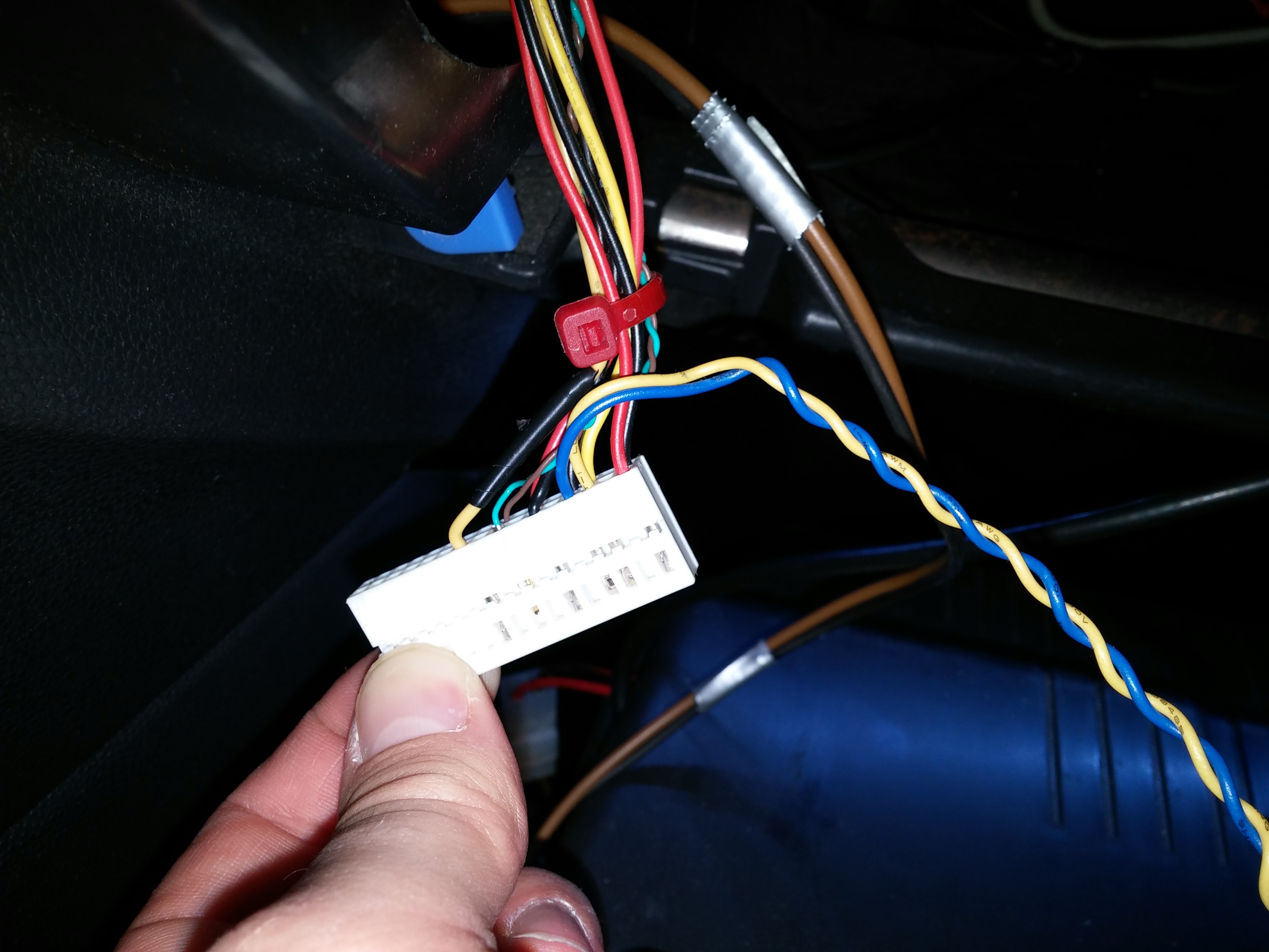
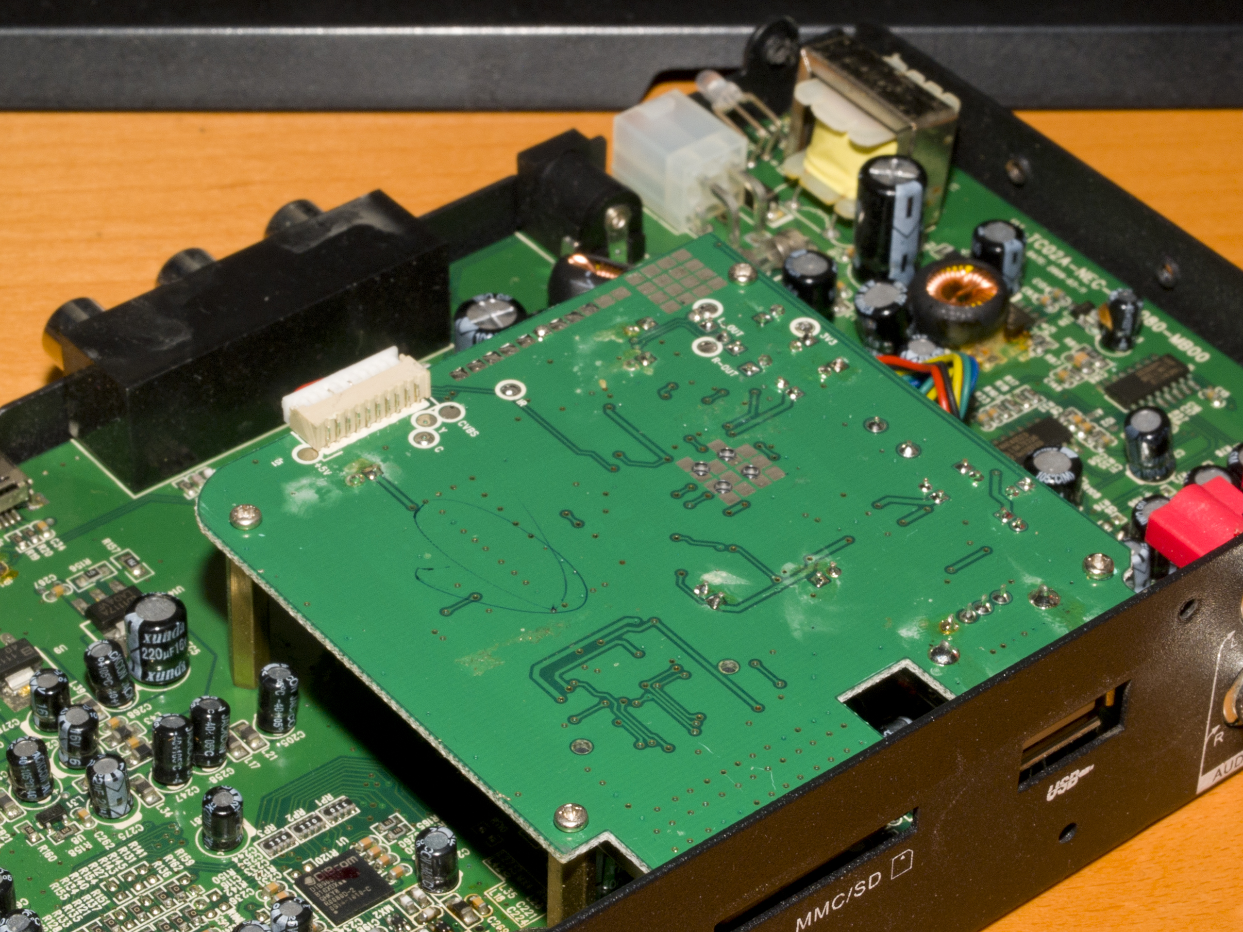
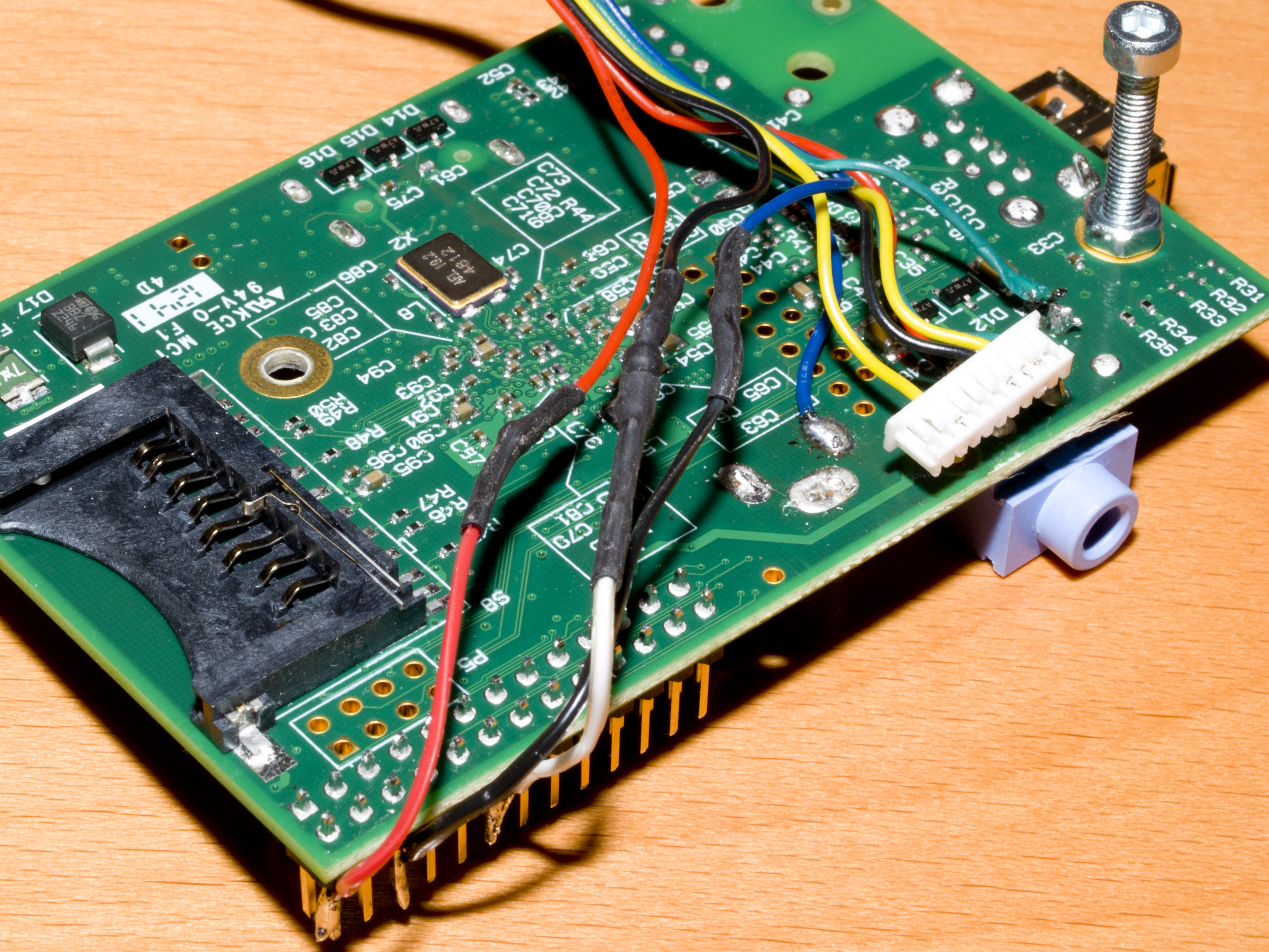
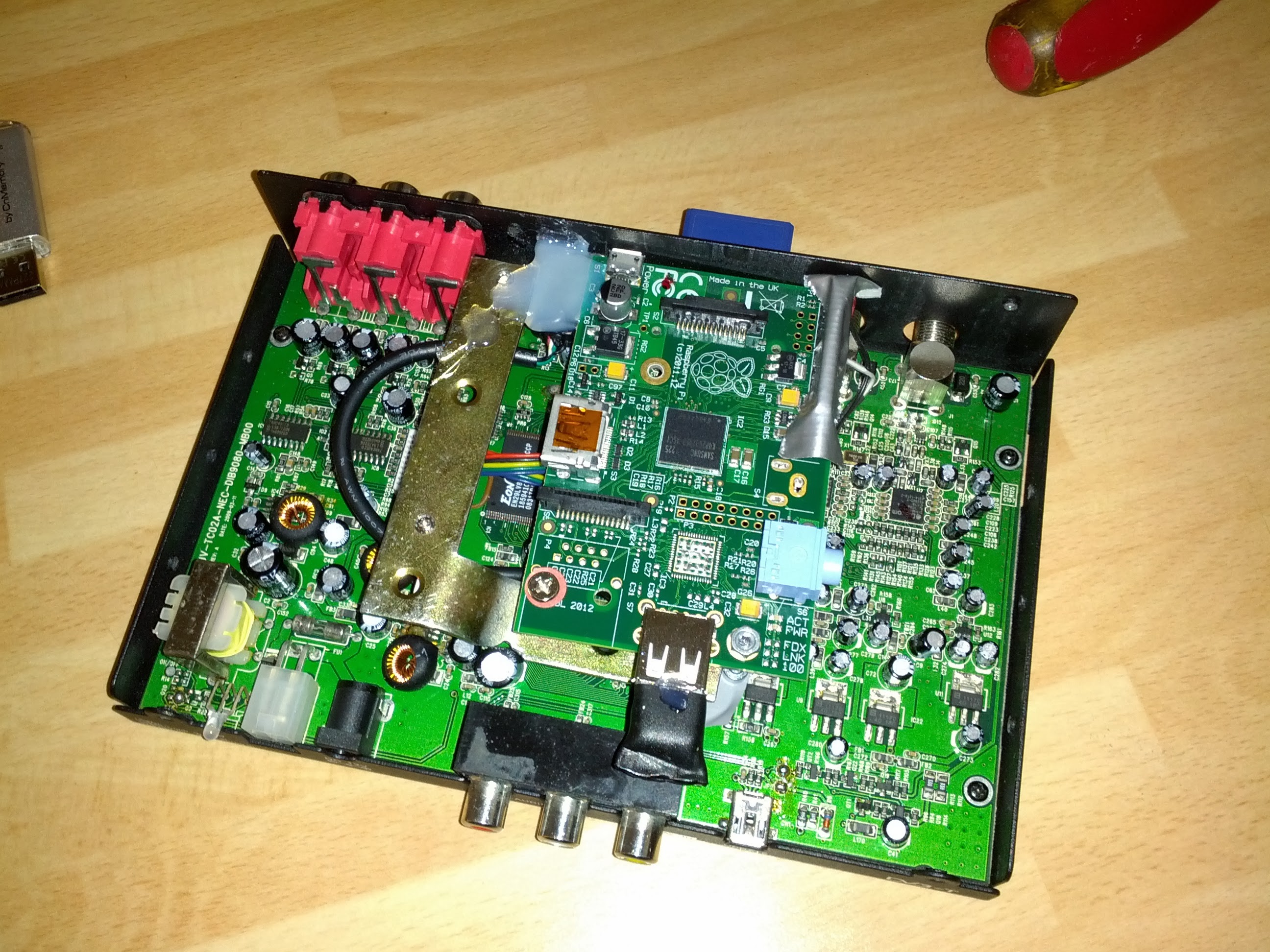
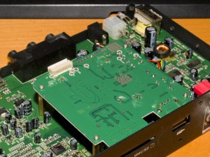
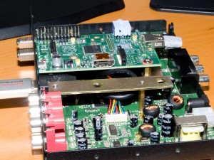
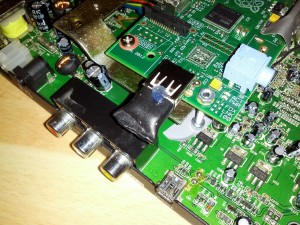
At the same day I got the idea, I took the receiver to my workbench and took a look insde. What I found there, really surprised me: The SD and USB-slots lead to a separate PCB what seams to be the media player:

OLYMPUS DIGITAL CAMERA OLYMPUS DIGITAL CAMERA


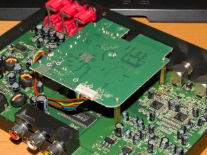
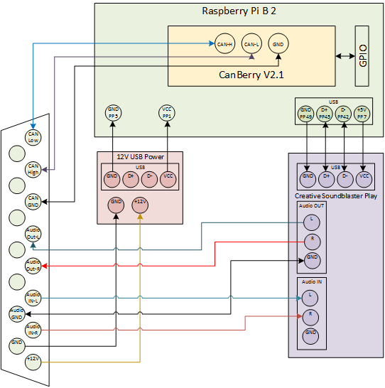
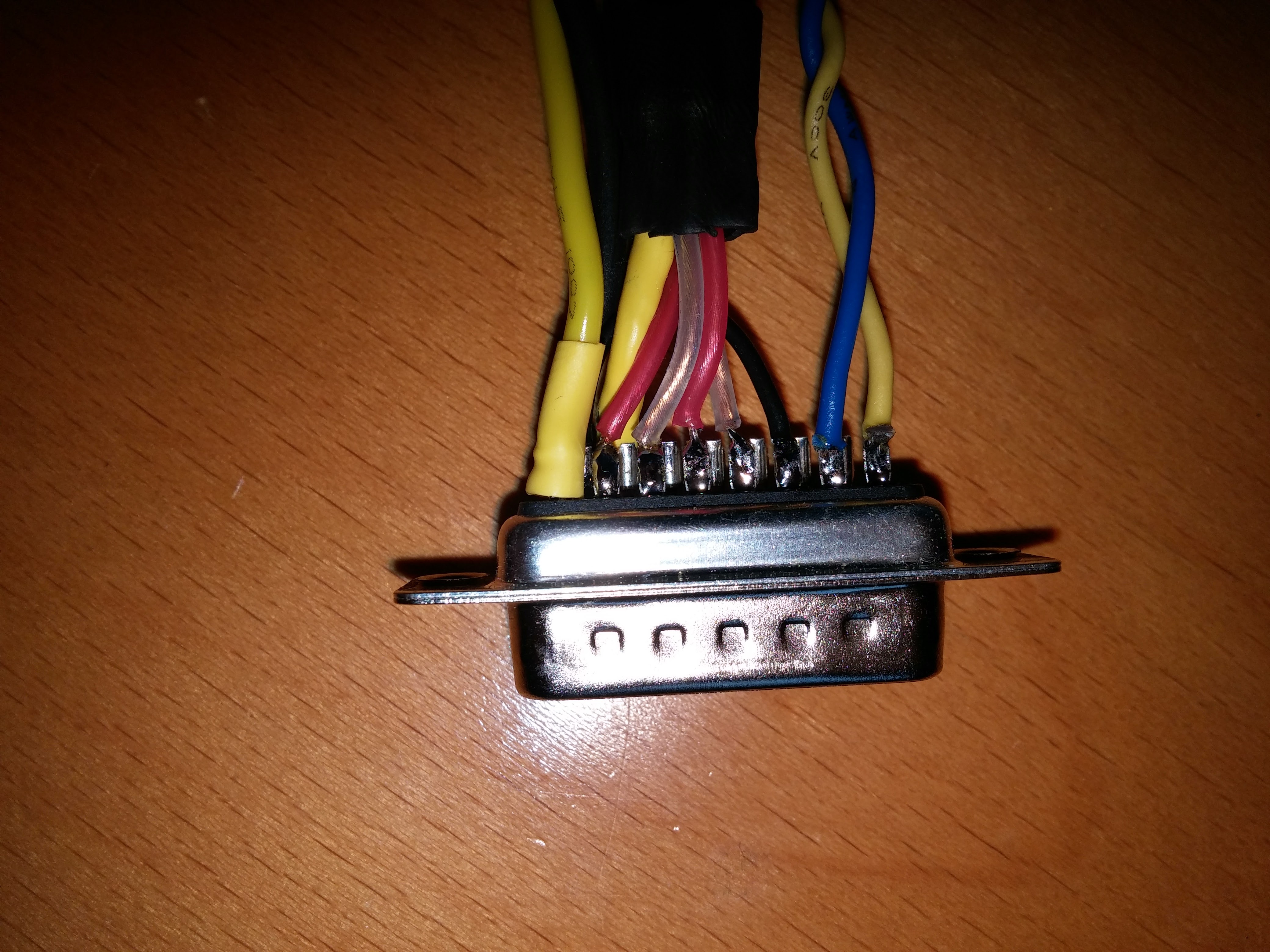
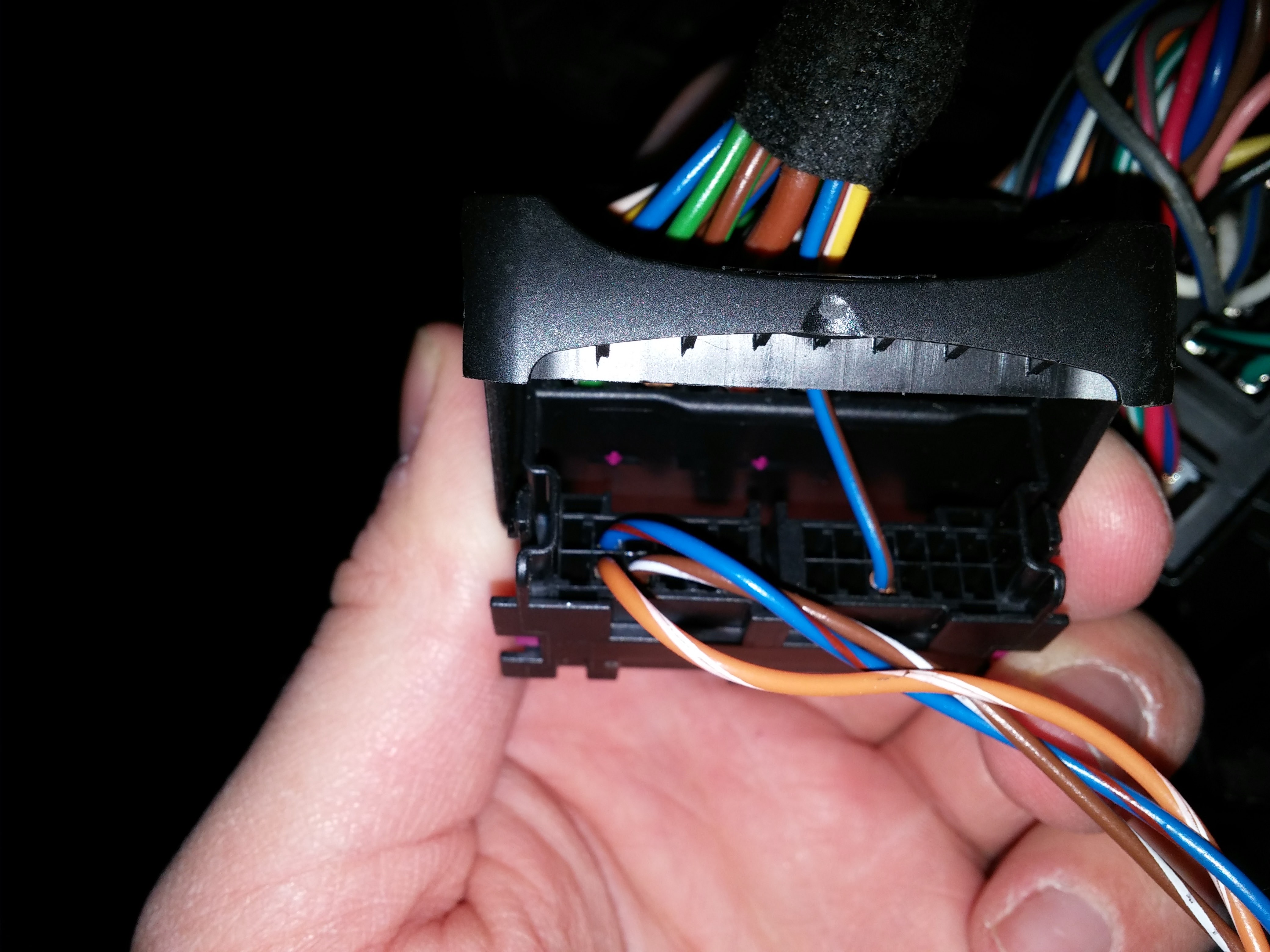
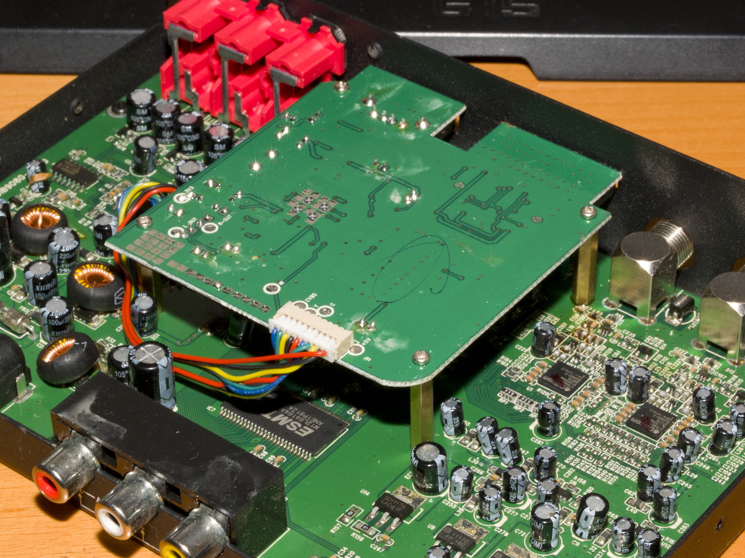
Motivated by this fact i started to figure out the pinout of the connector that connects the media player with the mail PCB:

1 – Blue: CVBS Video signal – looped to the video output on media mode
2 – Green: Y – Luma for S-Video (unused)
3 – Yellow: Ground
4 – Black: C – Chroma for S-Video (unused)
5 – Red: Right Audio signal – looped to audio output on media mode
6 – Blue – Ground
7 – Green: Left Audio signal – looped to audio output on media mode
8 – Yellow: +3,3V on media mode
9 – Black – Infrared Data – looped to I/R input on media mode
10 – Red: +5V on media mode

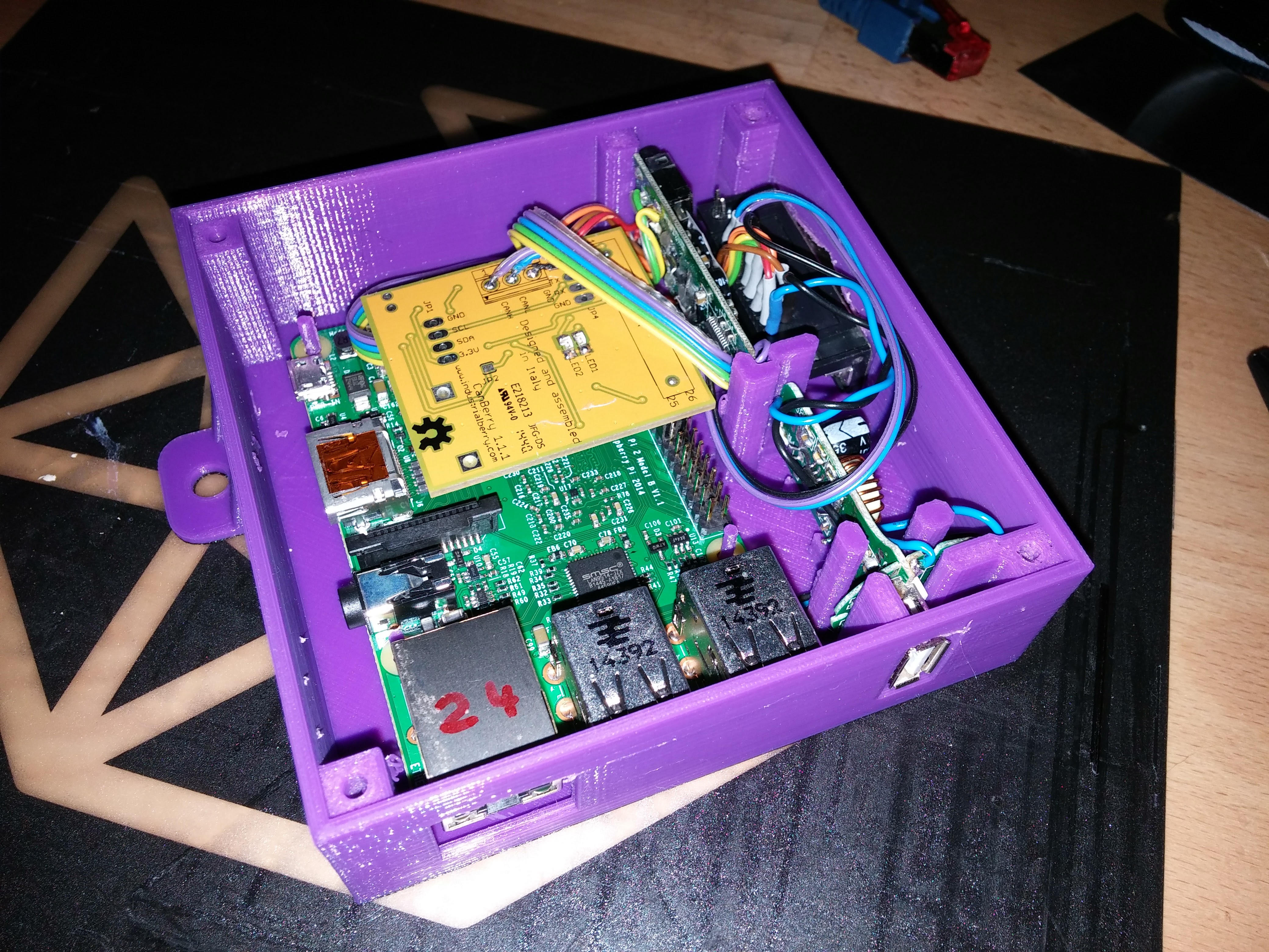
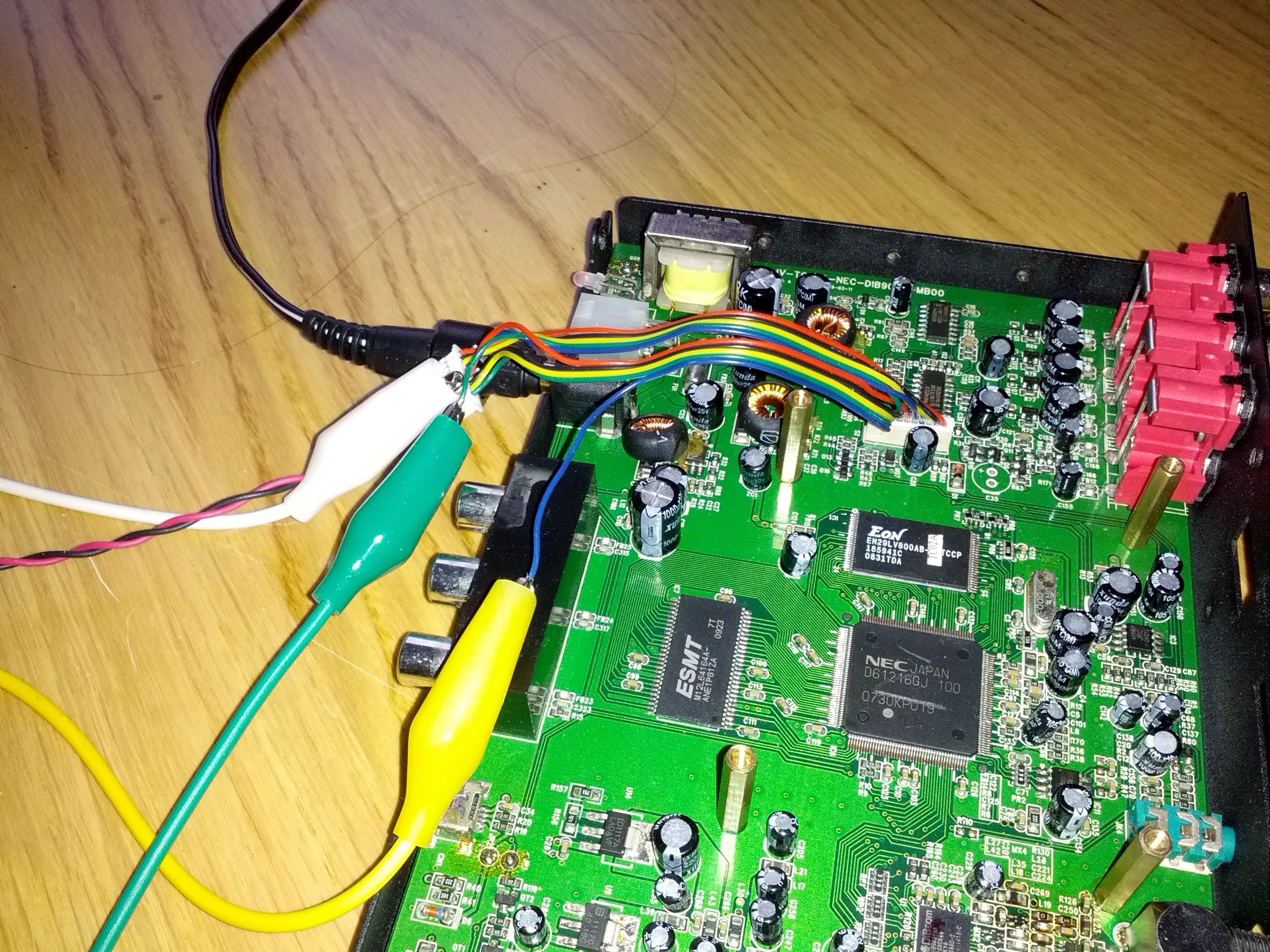
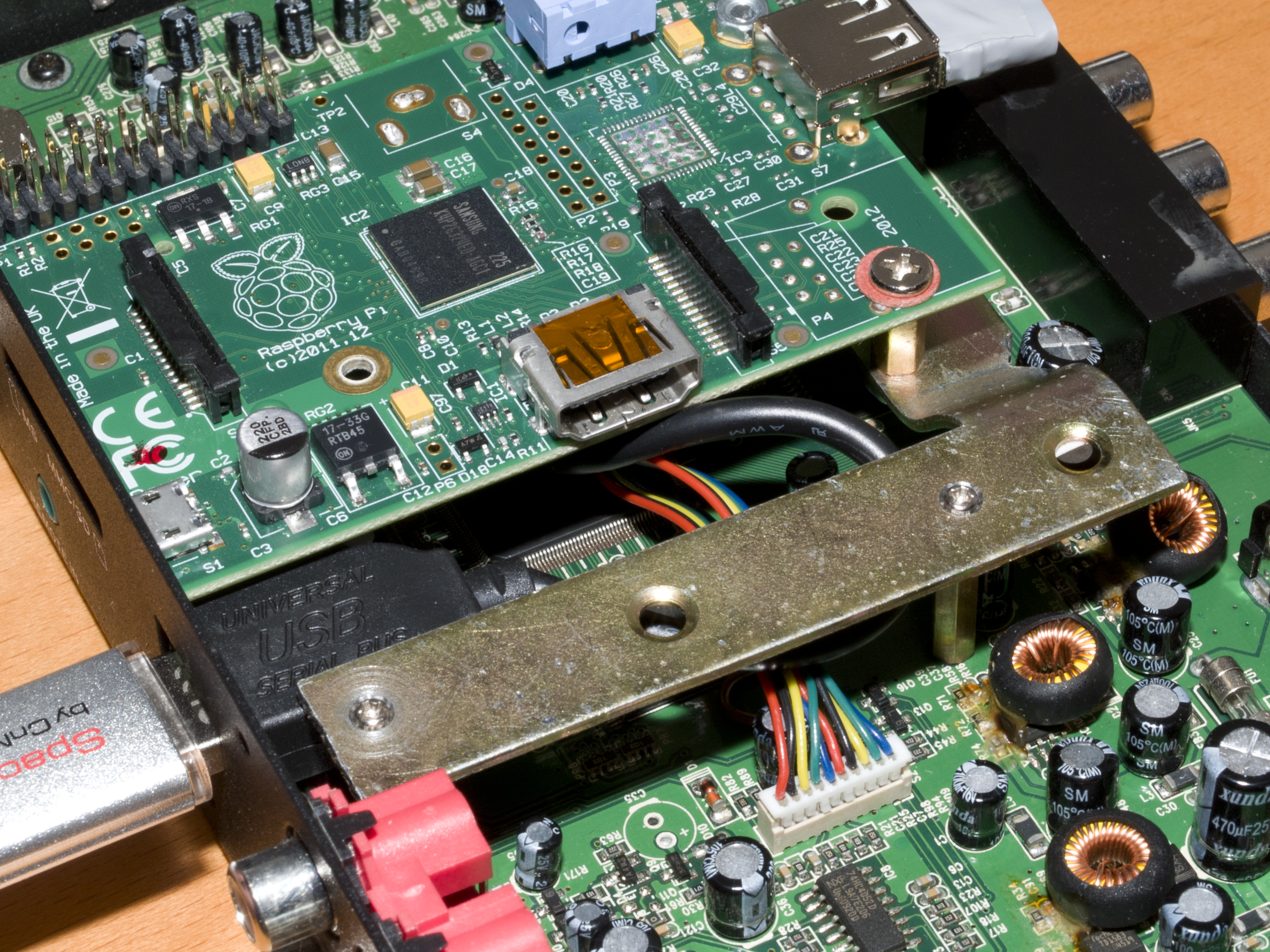
This turns out to be way more hackable than i imagined, time for a first test with a Raspberry Pi:

IMG_20131101_154401 IMG_20131101_154412 IMG_20131101_154437


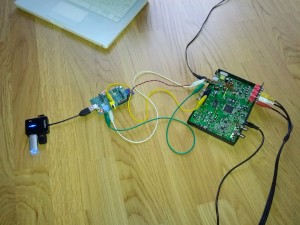
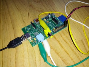
It worked! The internal 5V power source provides enough power to source the raspberry, a USB-hub, 32GB USB-stick, wifi dongle and a logitech wireless receiver!

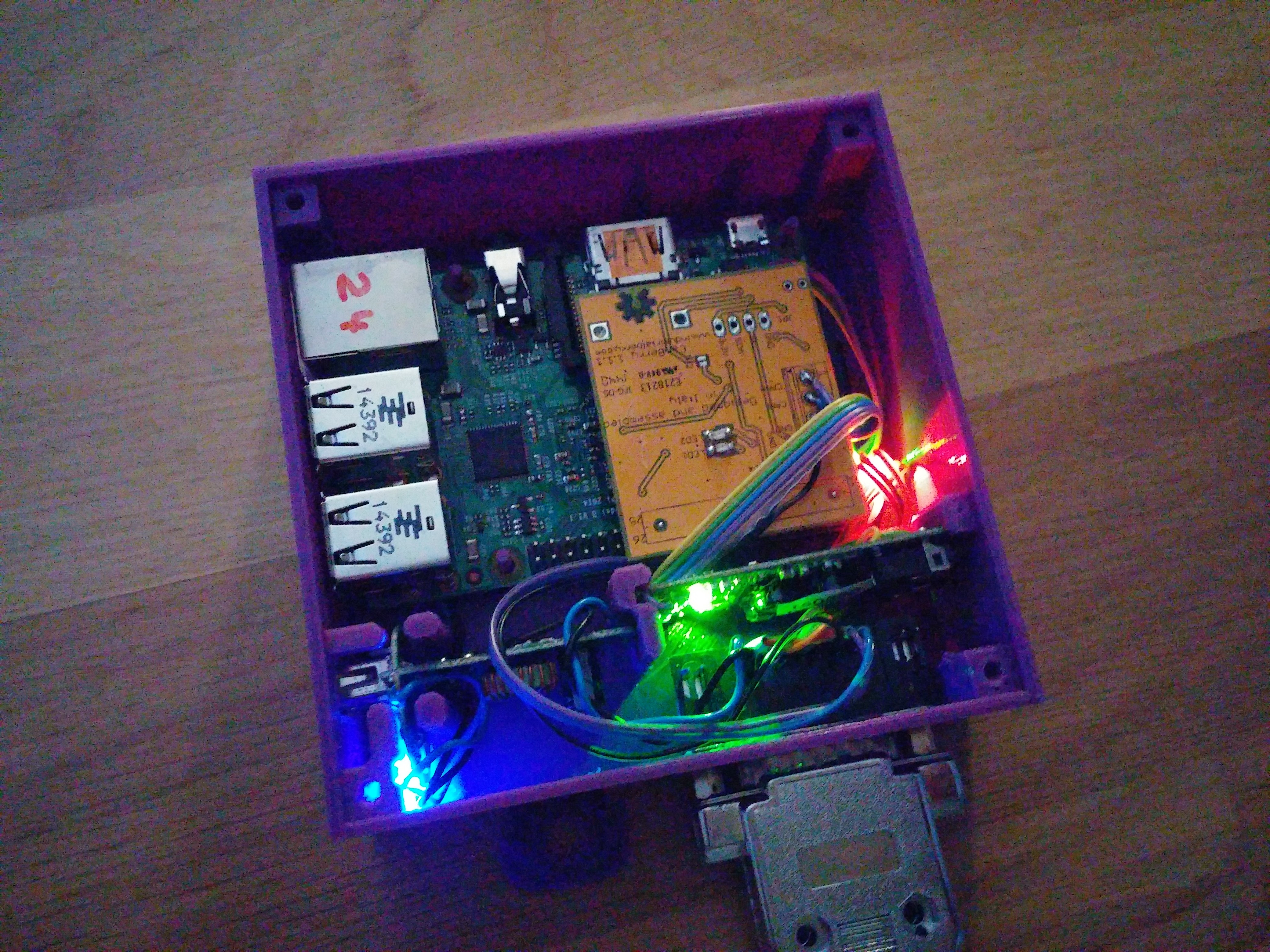
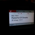
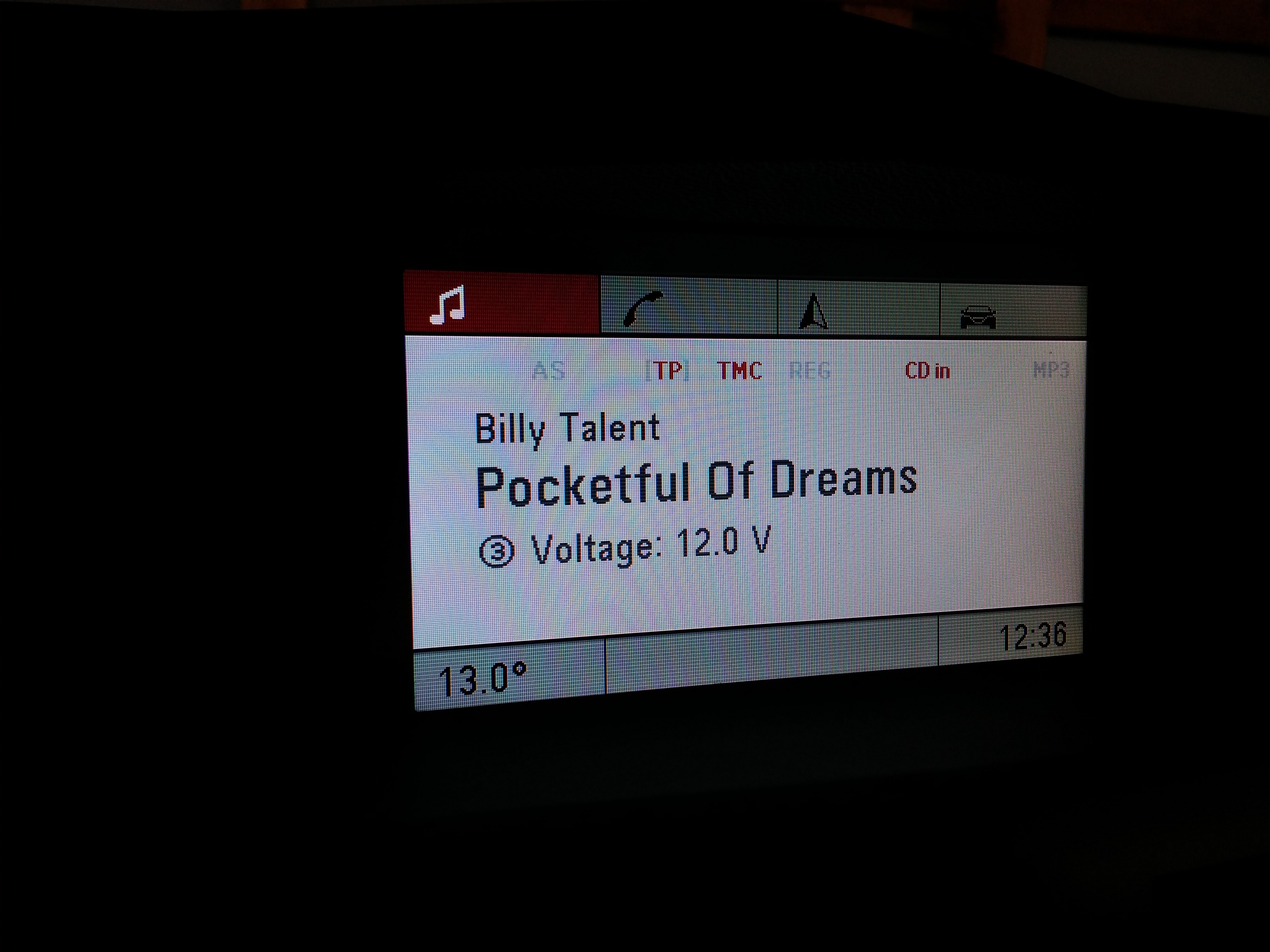
I can switch to media mode, the raspberry boots up and provides a good image and sound quality (as good as the internal sound device…).
Next test is the remote control with the original infrared remote. The “eye” seams to be a very usual I/R receiver, running on 5V,  the data line is directly looped to PIN9 of the connector.
To protect the 3,3V GPIO-Pins of the raspberry, I connected it with a 4,7K resistor to GPIO18 (pin 12) and used the lirc_rpi module an lirc to read it.
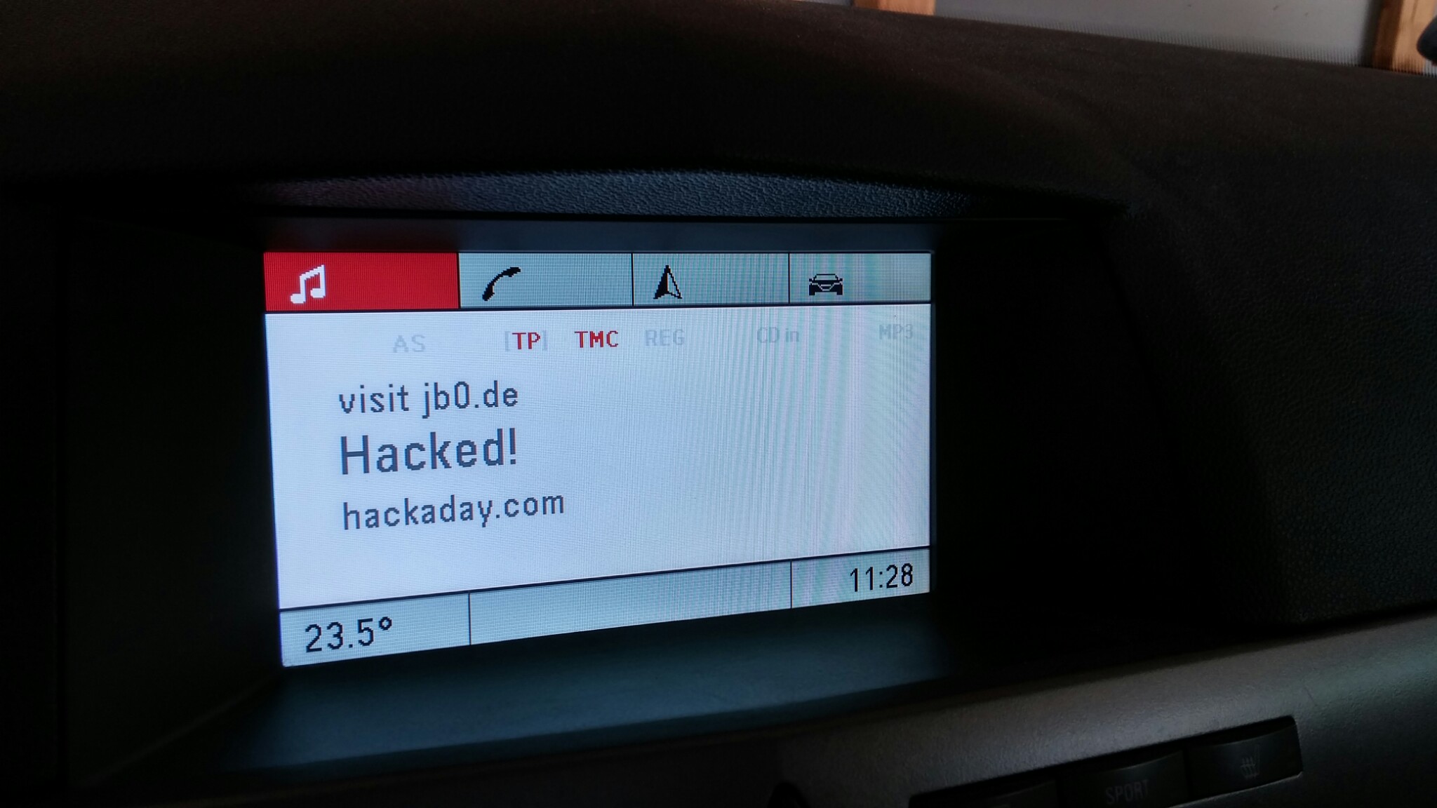
At this point I’m really starting to wonder about this project, because even that works perfectly on first try! (I will add another post about the Software, including the lirc configuration!)

No doubt, this concept is proofed!


The Build

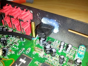
Before I could put all components together, there is one small thing to fix at the main PCB: The power to the raspberry is only provided in media-mode and was cut immediately when switching to TV.
I identified the responsible transistor and just bridged it:
OLYMPUS DIGITAL CAMERA

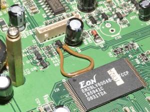
Now the raspberry boots up when the power is connected (what is actually my ignition, later more).
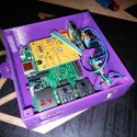
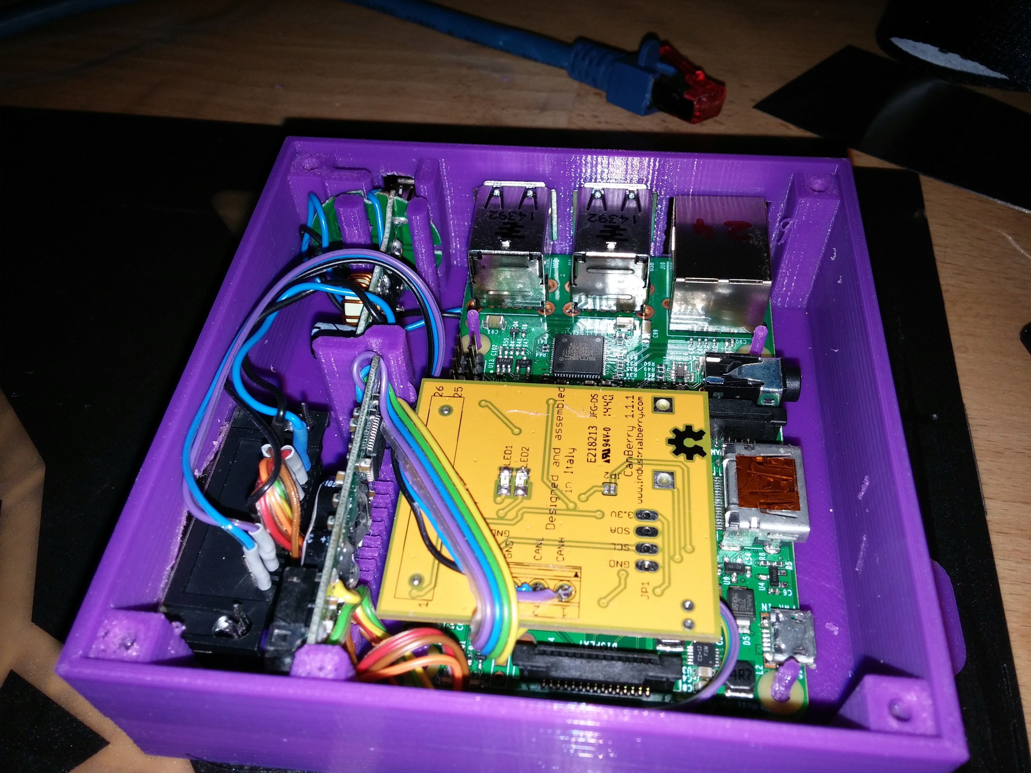
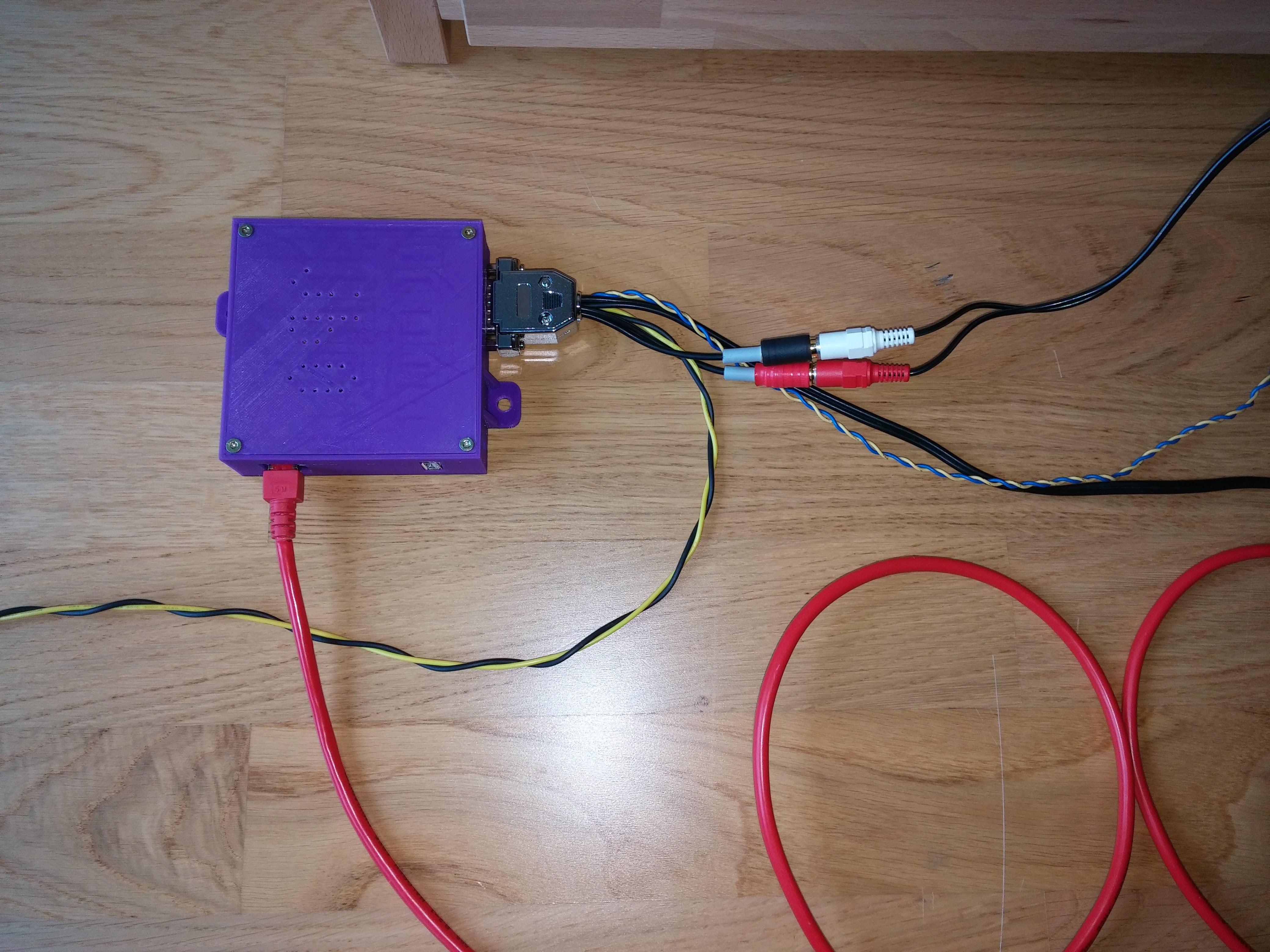
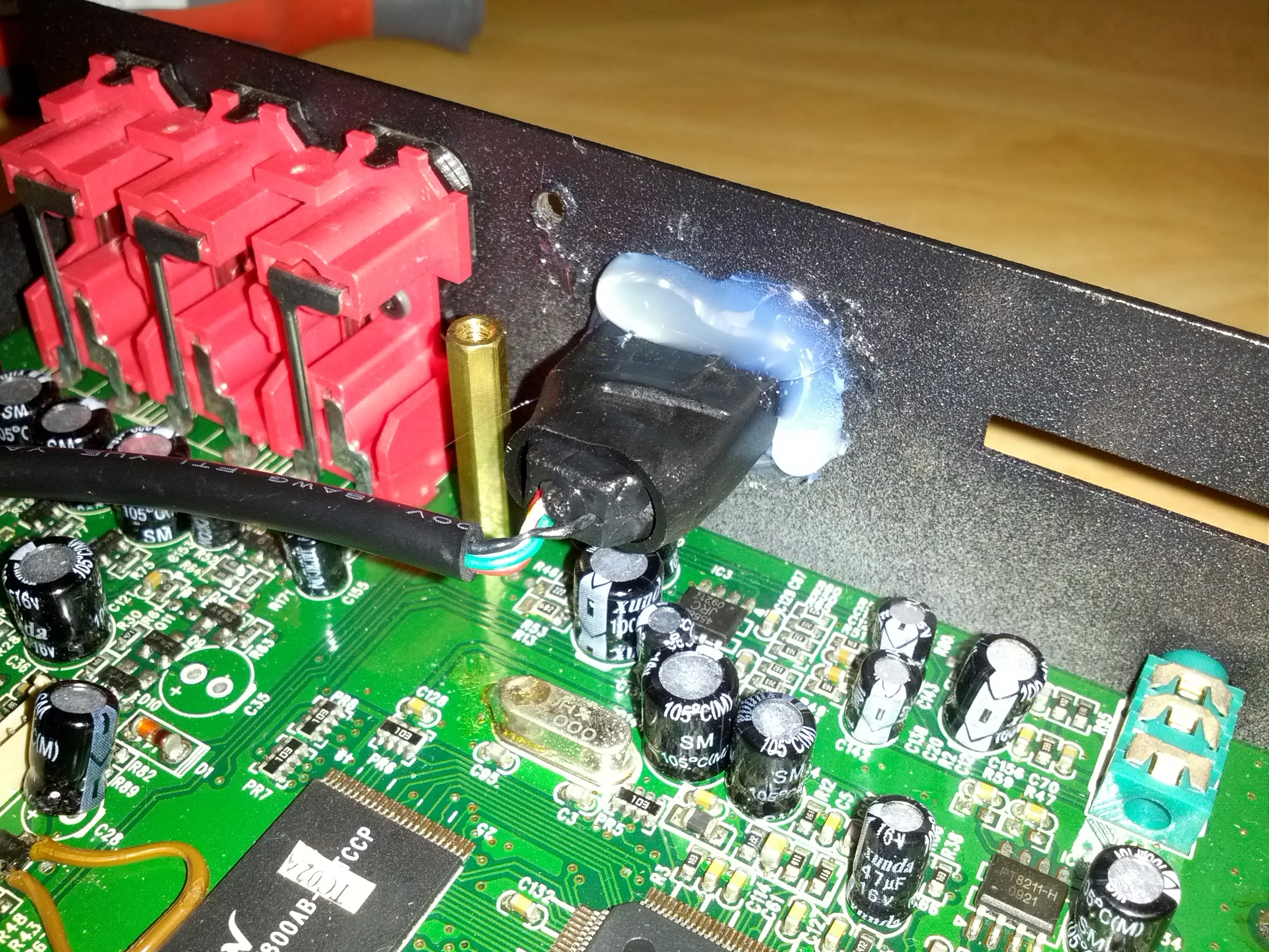
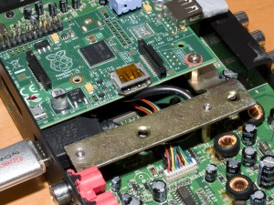
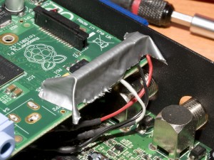
Time for the wiring of the Pi (I needed to remove the CVBS-Connector to fit the Pi inside the housing!):

OLYMPUS DIGITAL CAMERAOLYMPUS DIGITAL CAMERA

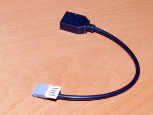
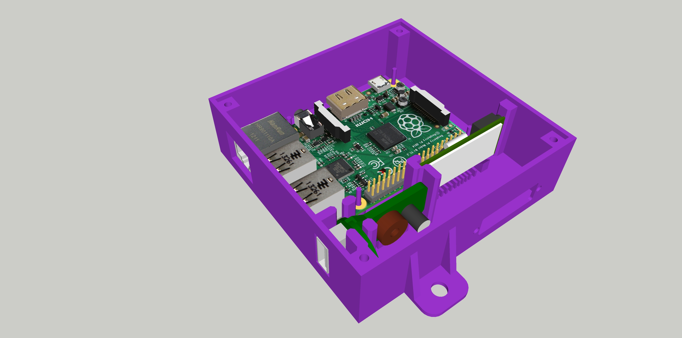
The USB-Connector was too long for the housing, so I adapted it to fit!

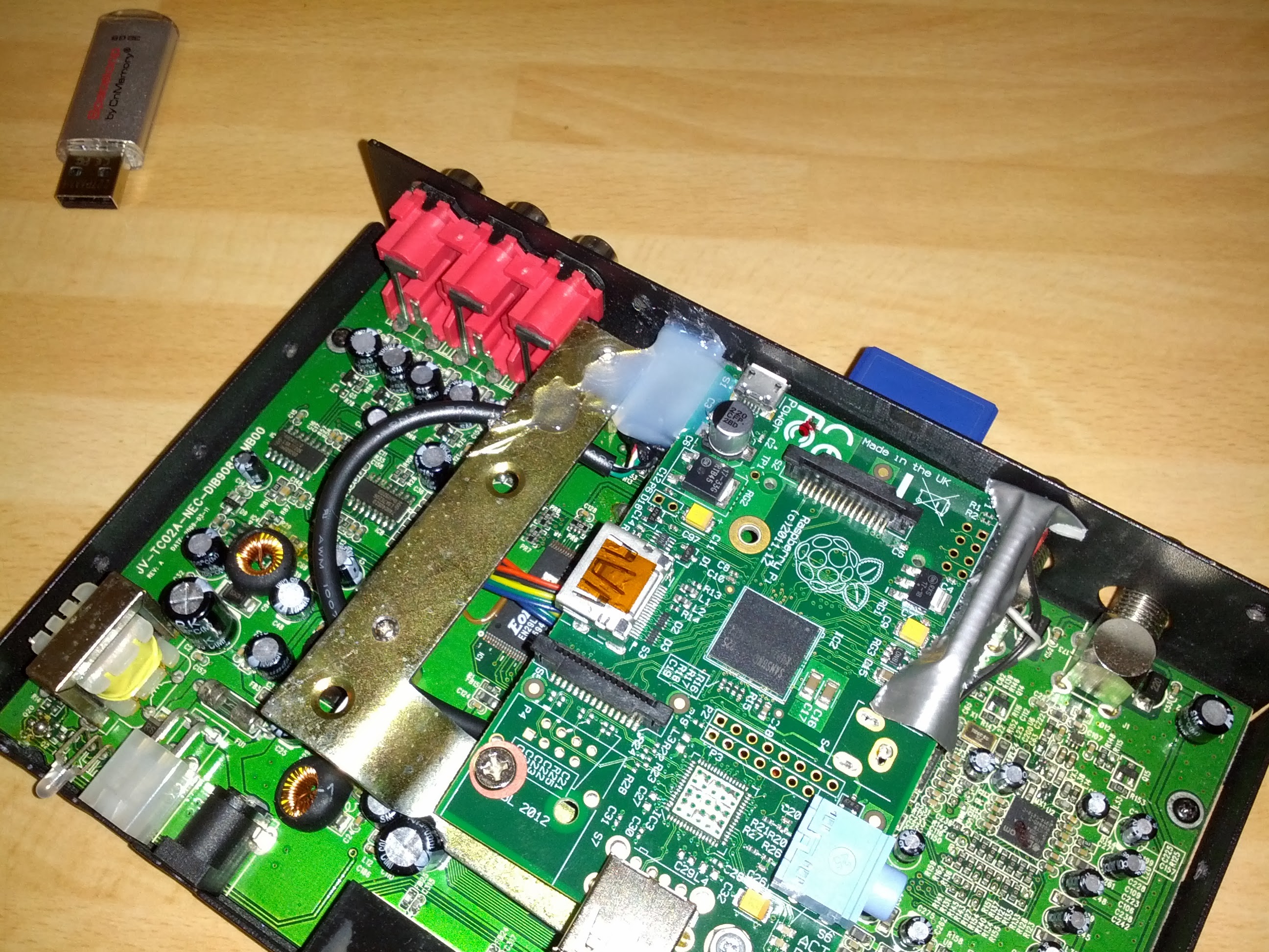
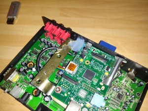
To hold the pi in position, I made an adapter out of a piece of metal from the hardware store:
OLYMPUS DIGITAL CAMERA OLYMPUS DIGITAL CAMERA

Some work on the USB-port, isolation for the GPIO-Pins, shrink tube and hot glue:

OLYMPUS DIGITAL CAMERA IMG_20131102_170634 IMG_20131102_172053IMG_20131102_172059 IMG_20131102_172105

The cage of the USB-Port is bend around the hole in the housing to hold it in position, I will add a picture of that later… (maybe)

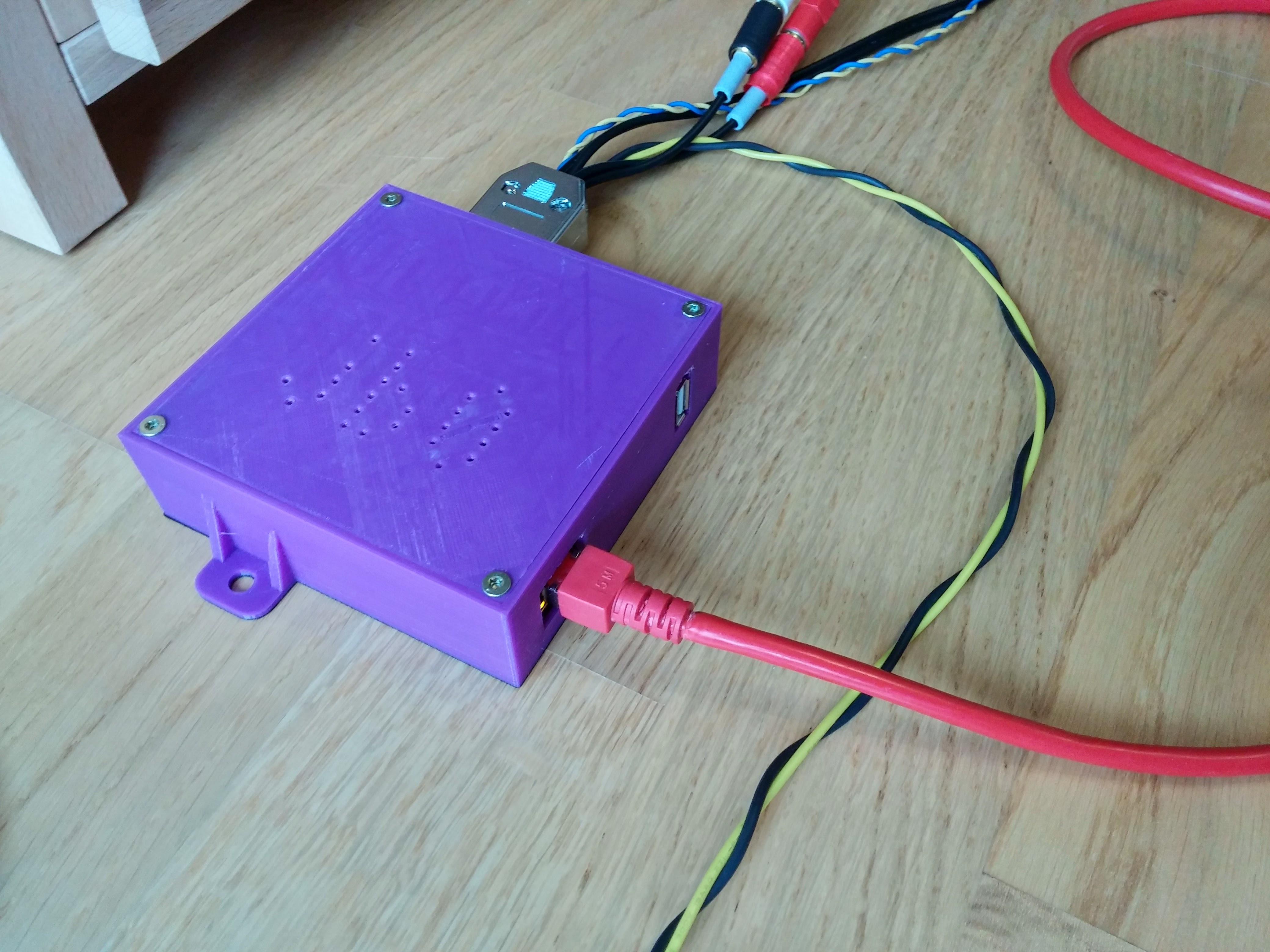
Thats it! The hardware is ready, so far.


Next steps

I will soon post about the software used on the raspberry.
The device is powered with ignition what means that the Pi will boot when the ignition is turned on. To shorten the time that it takes to start playing music, I have planned a little circuit that powers it on after unlocking the car.
Another planned project is to use my old android smartphone as a head up display and Wifi hotspot. Having internet in the car could also bring some more features to the raspberry like dropbox music sync, weather information etc.