Previous: Display additional data
Hey there, I finally managed to upload source files for my Project!
The program currently listens for the previously mentioned diagnostic data. The Requests are send outside the program. I will change that when i figure out how to get the data without activly asking for them. Just by observing the bus.
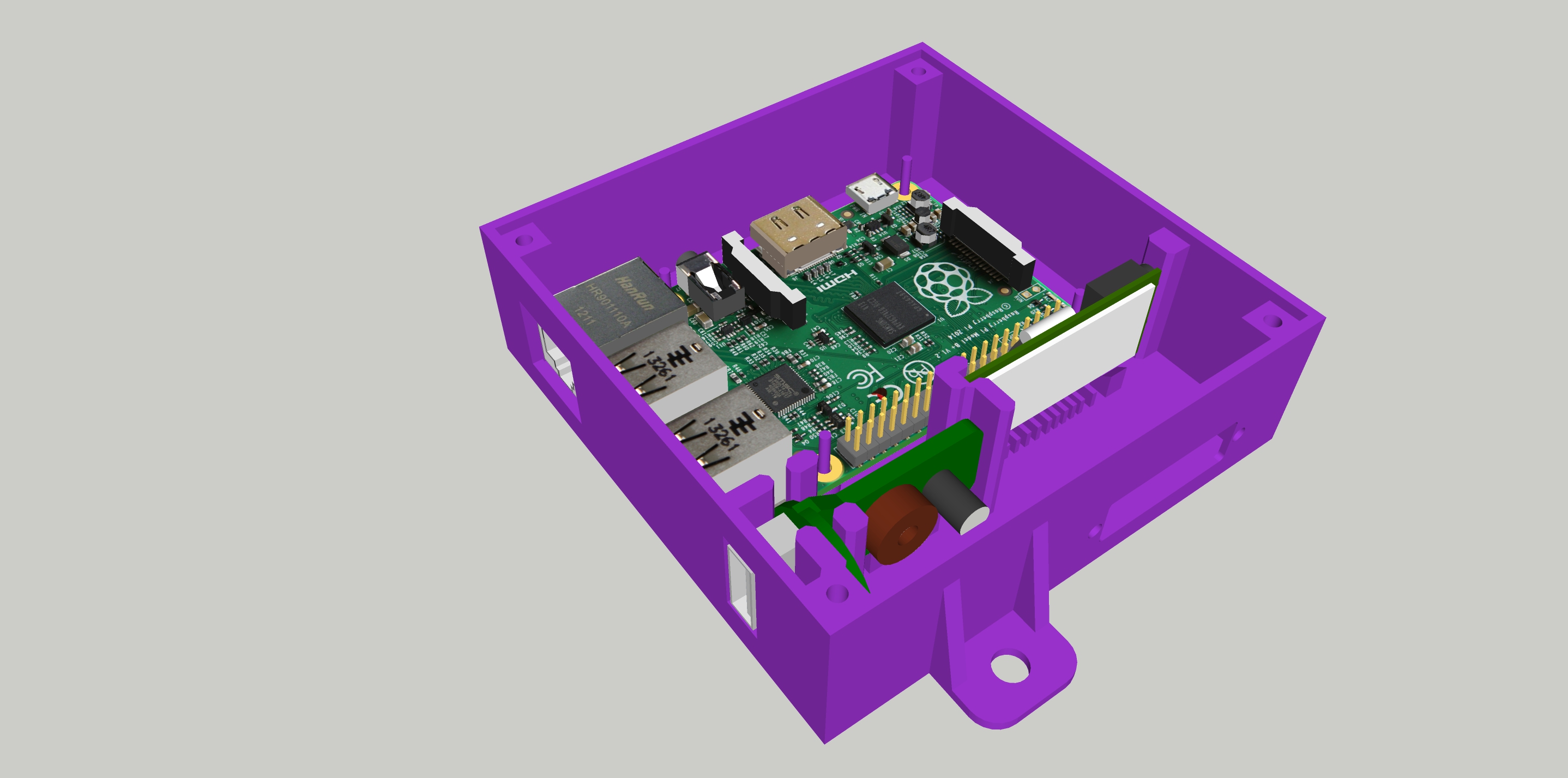
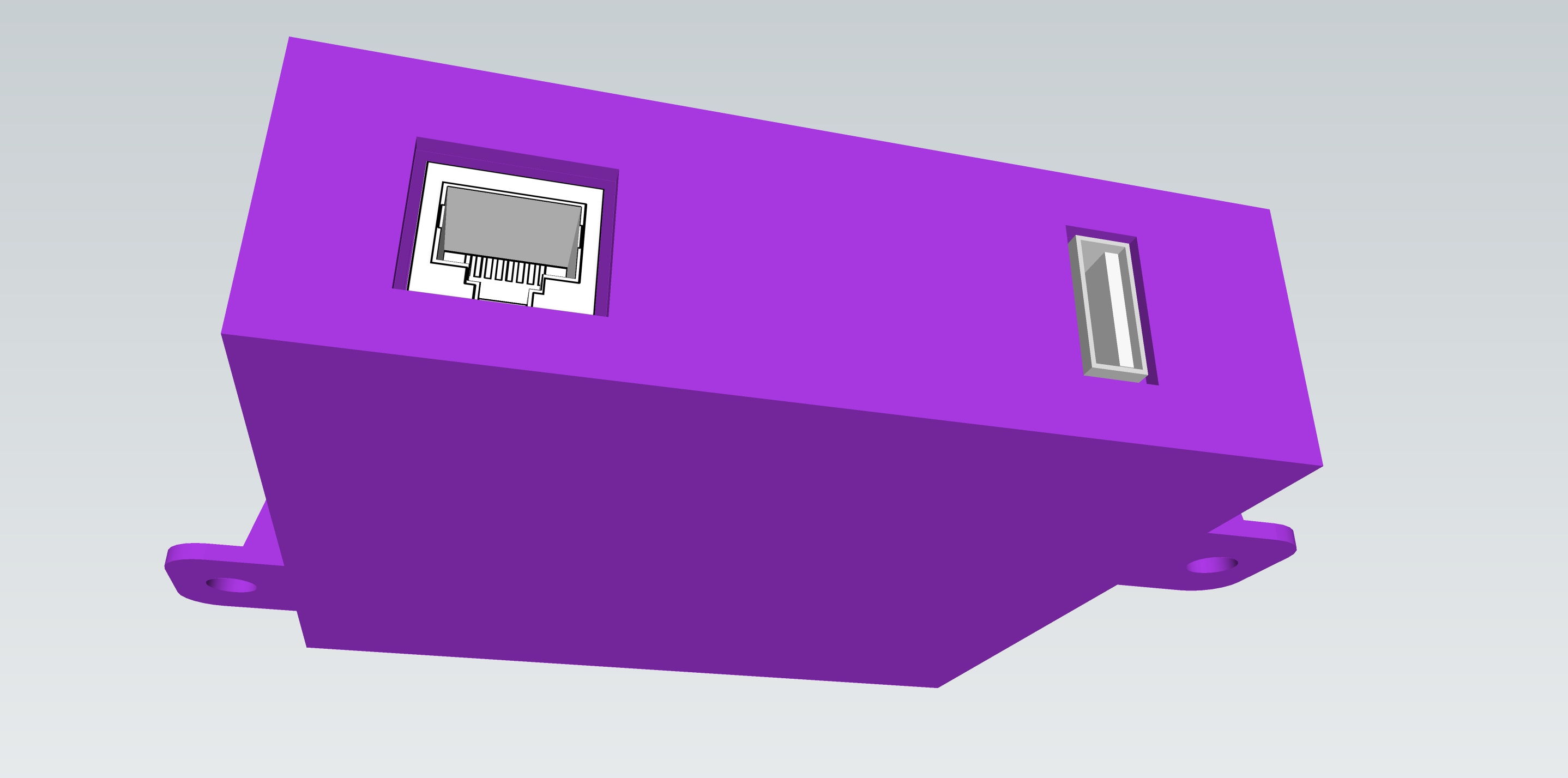
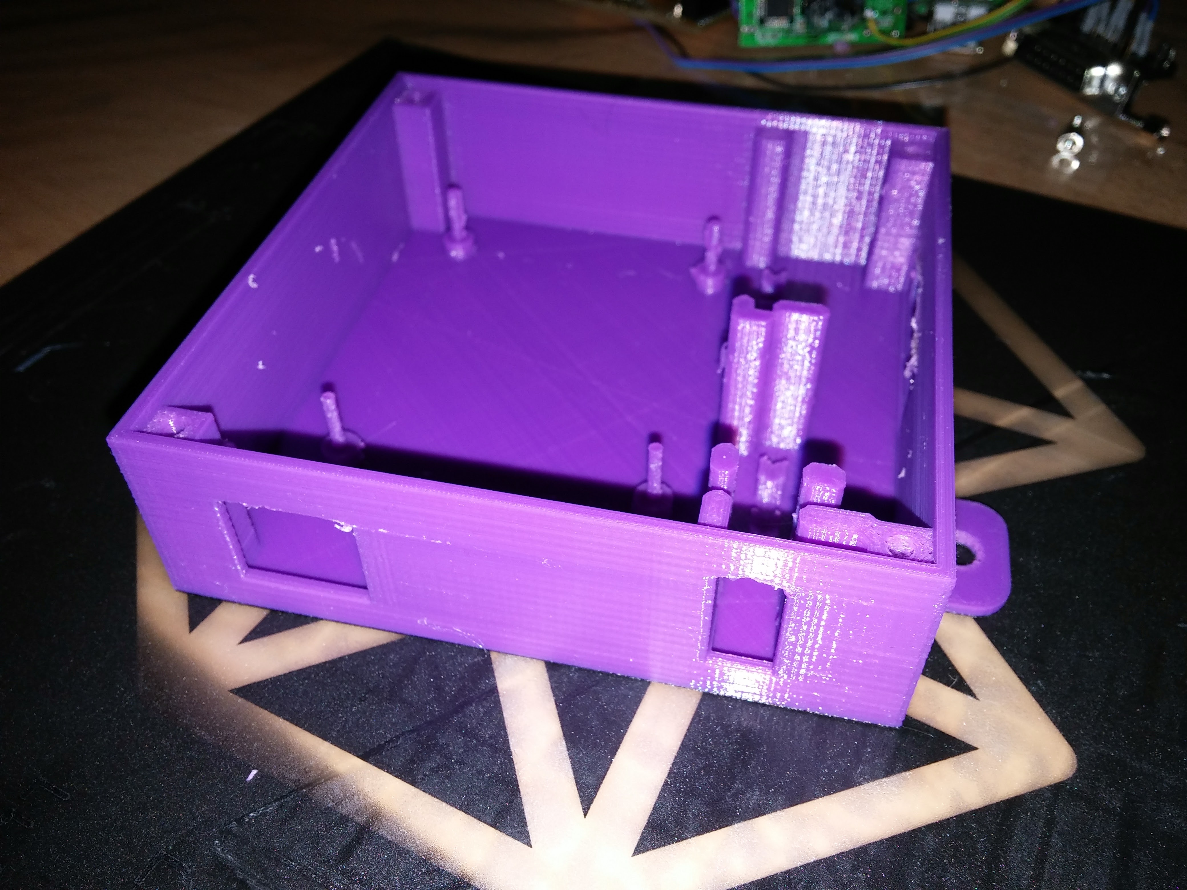
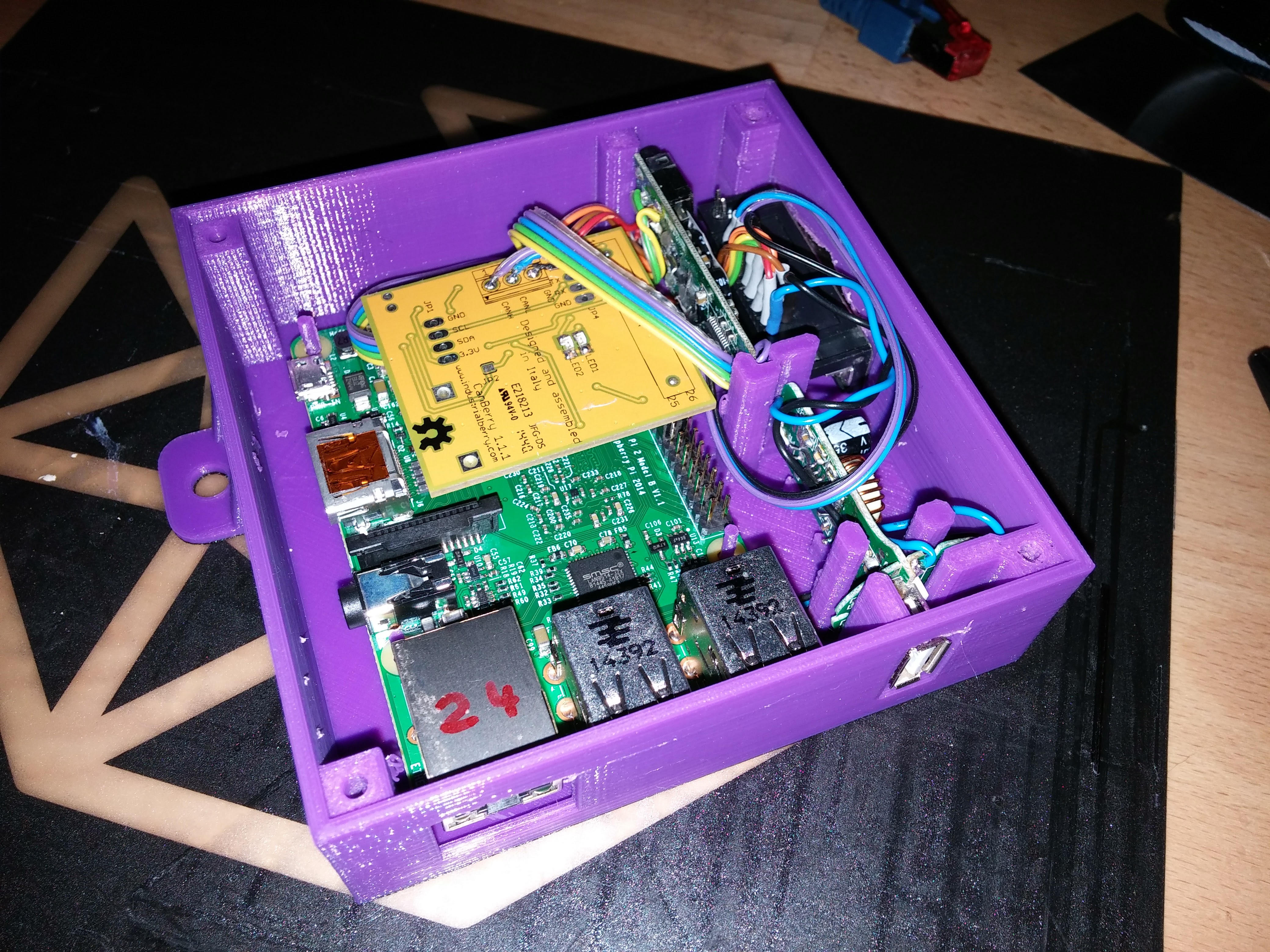
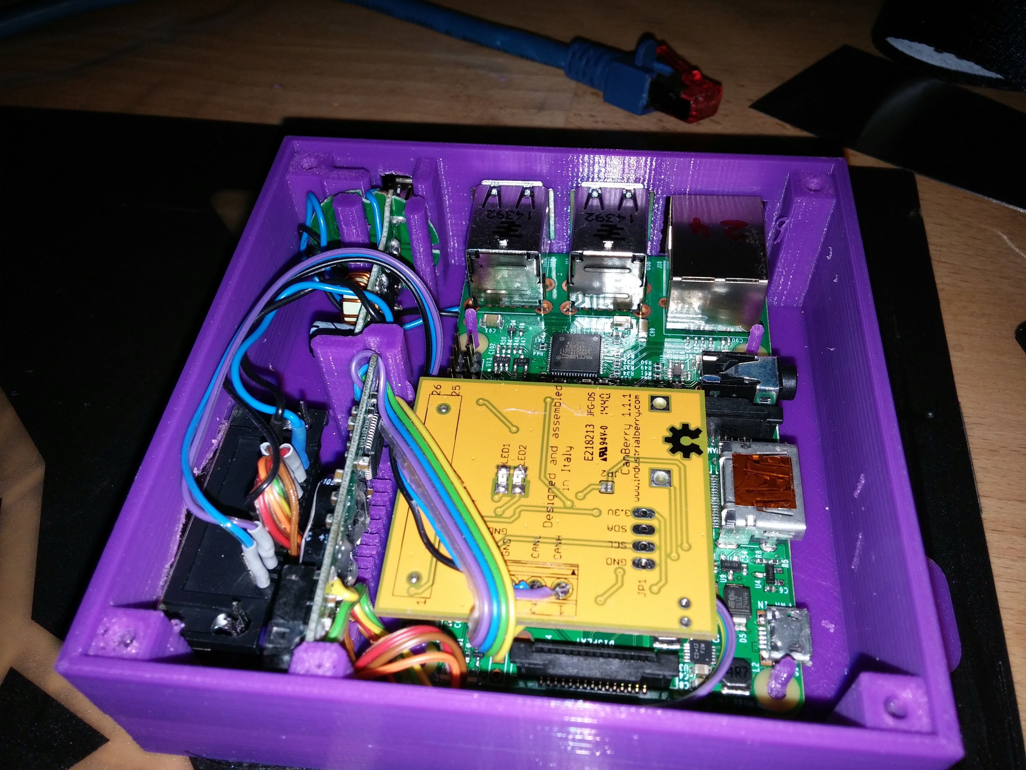
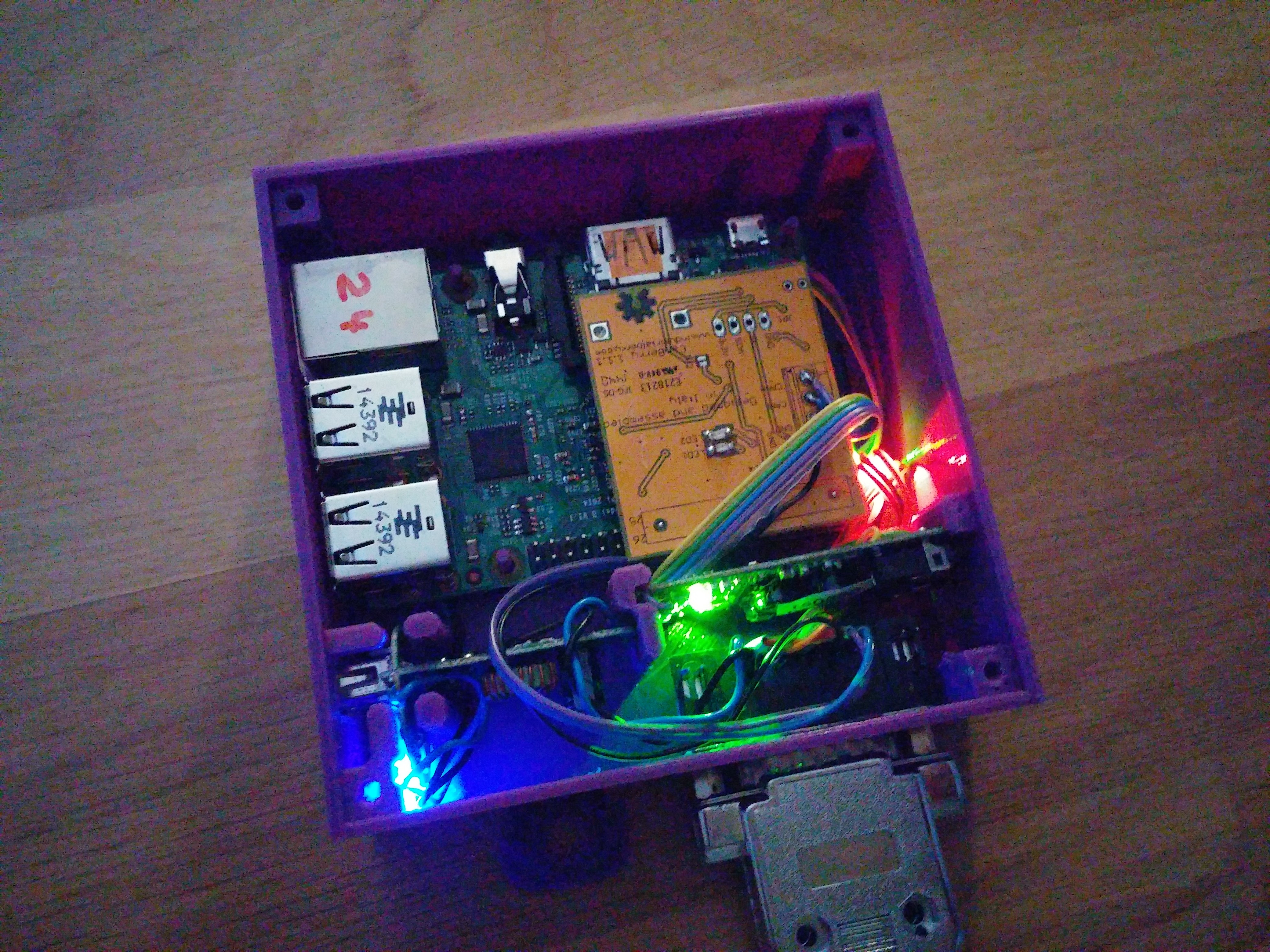
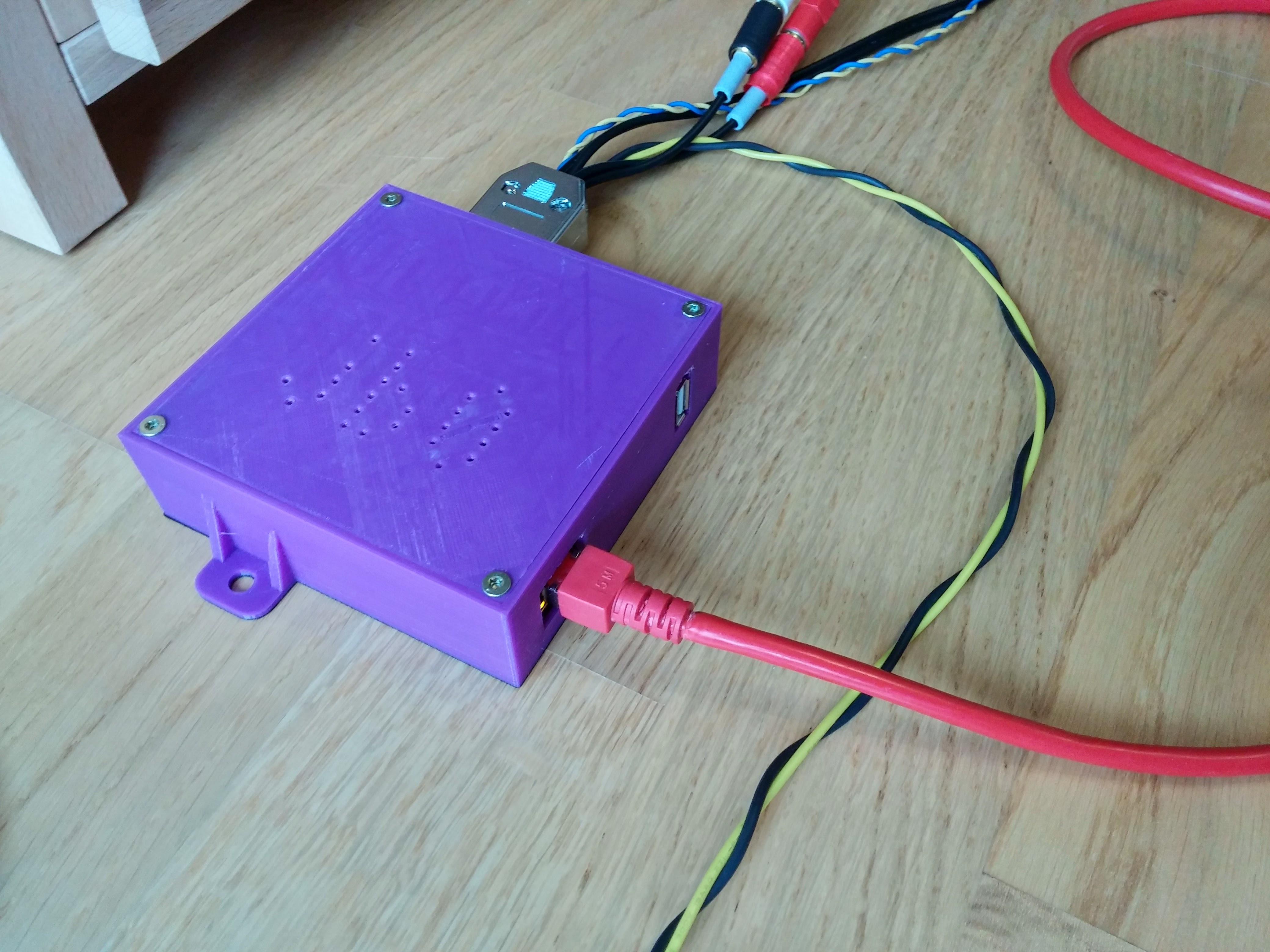
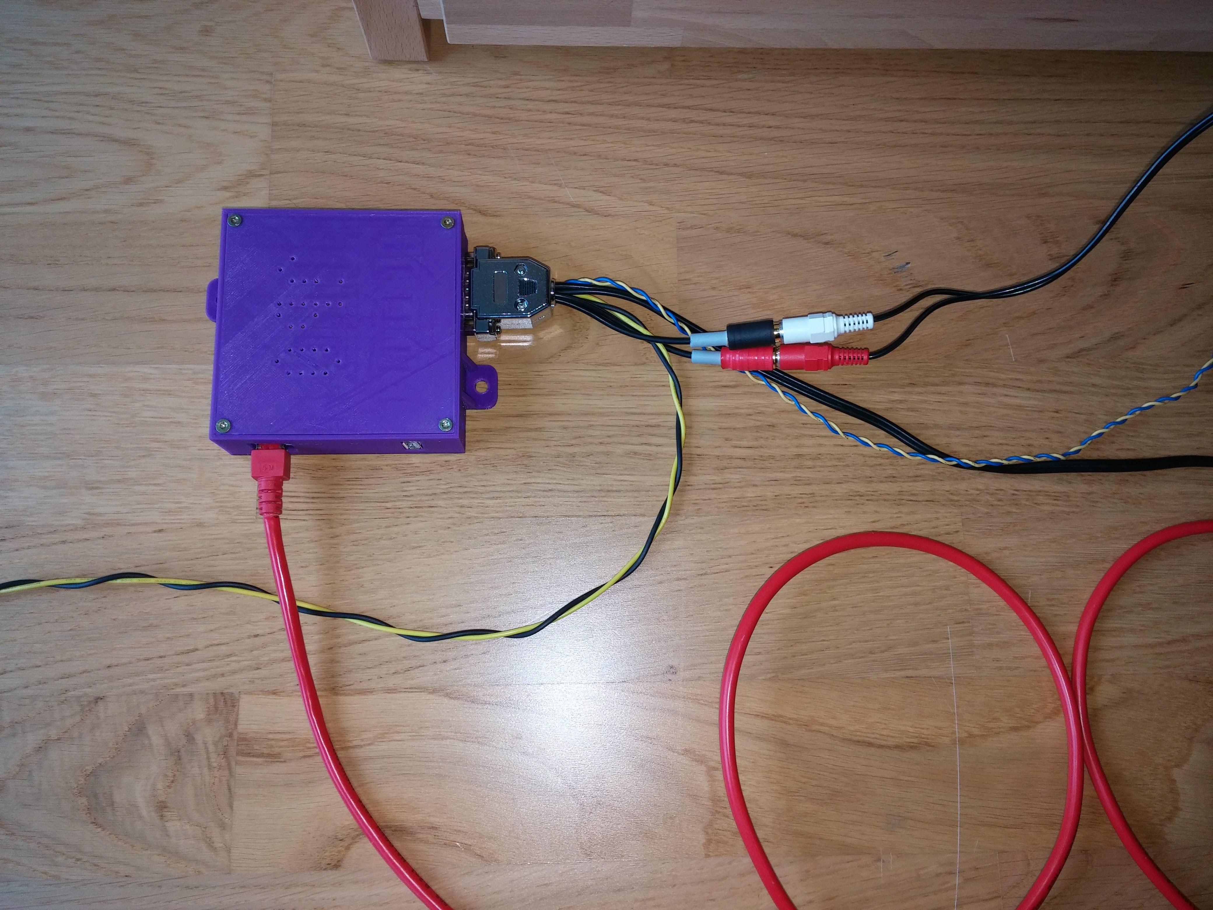
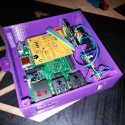
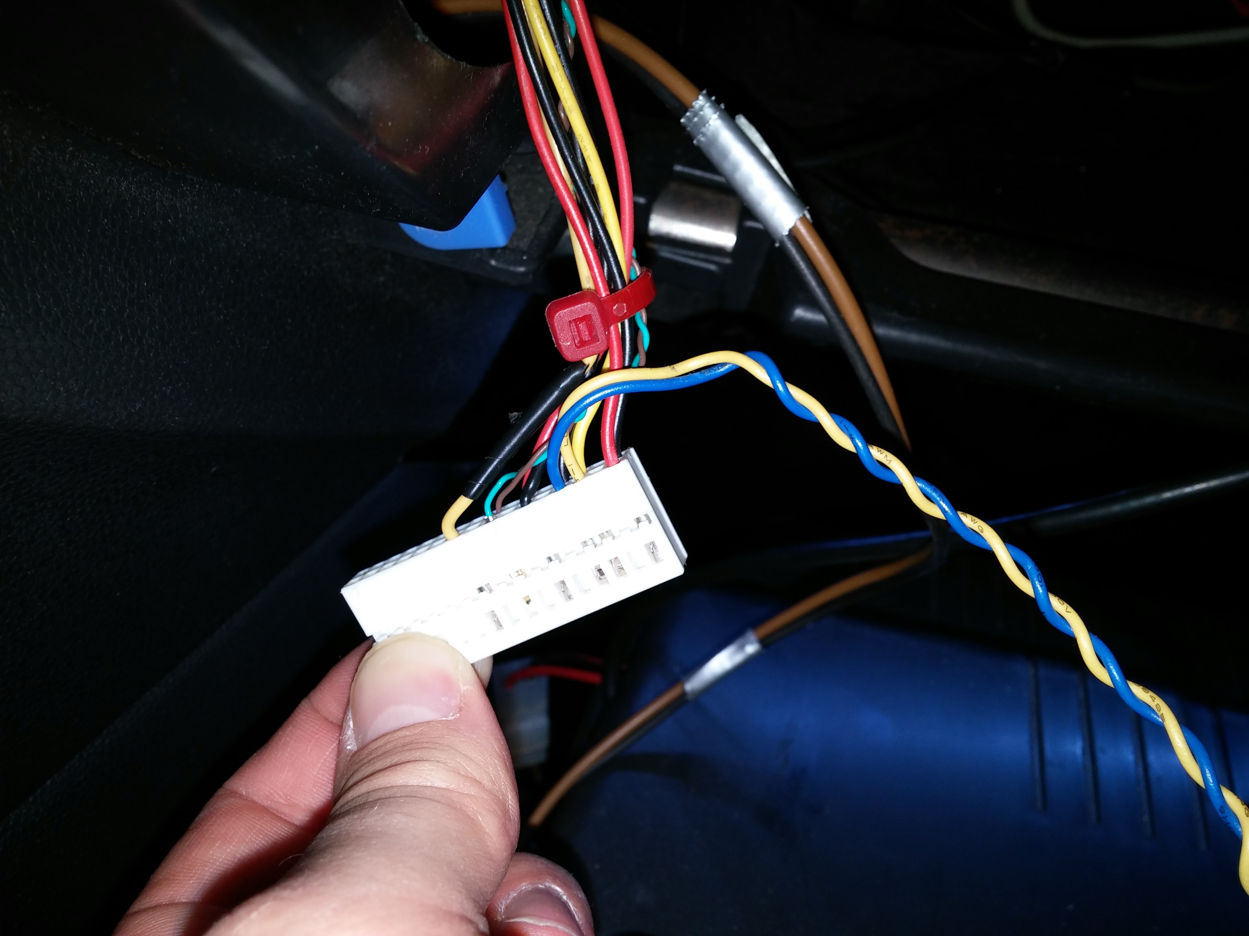
As you can see above, there is also a housing for the raspberry and the other components. The system is now installed hidden in my car, directly connected to the entertainment bus and the aux-in of the headunit.
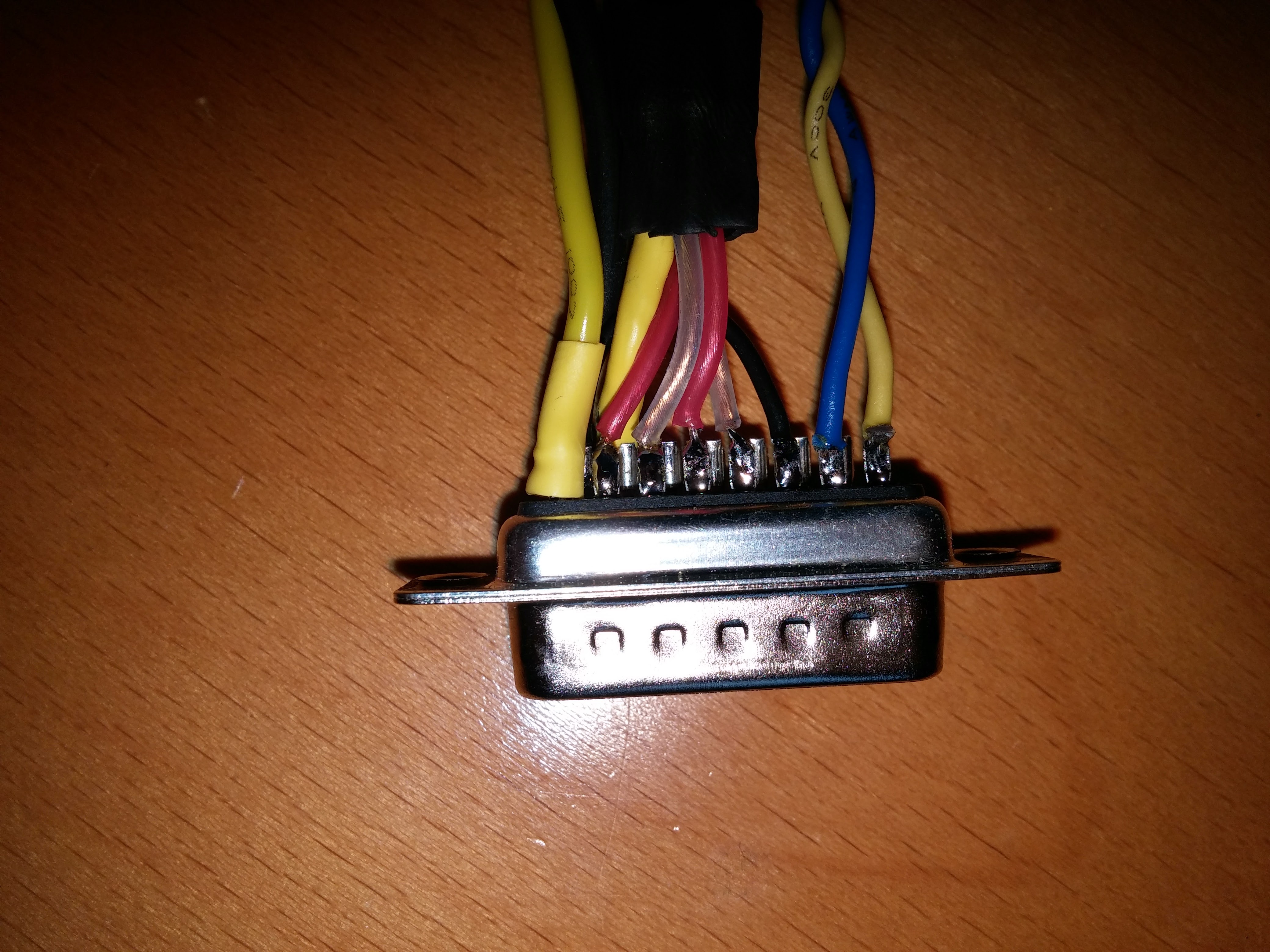
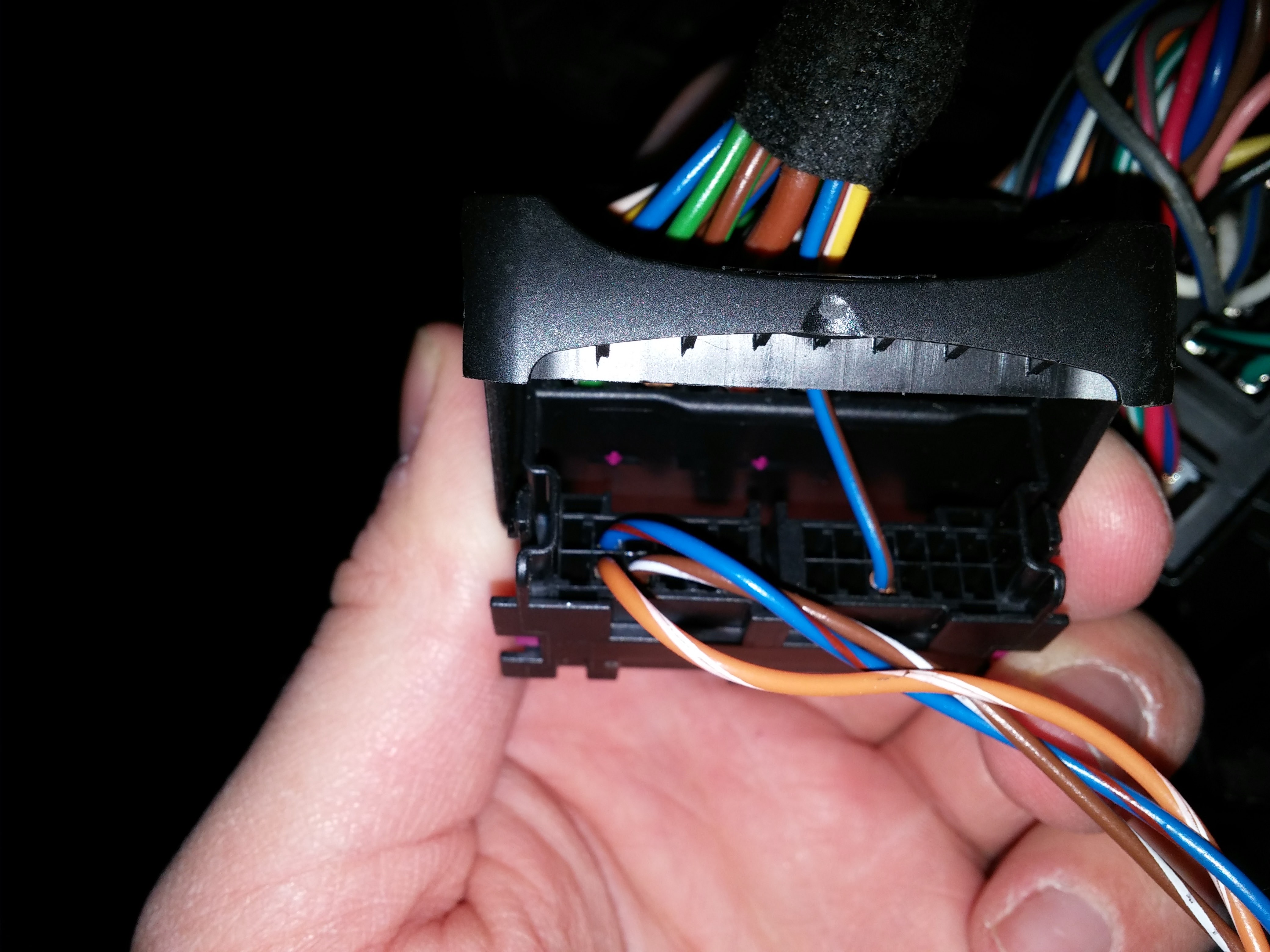
The Connection is made with a 15-pin d-sub connector as follows:
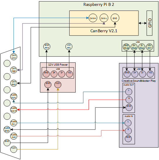
The audio in connects to the audio out of my tv receiver, the 12V are from the power source for the interrior lighting. This line will be activated when the car gets unlocked and stays active for about 30 minutes after locking the car. So the components won’t stay active all the time and drain my battery but will be available as soon as I enter the car.

My 12V USB adapter has two USB-ports. One was dissoldered and connected directly to the raspberry solder-pads PP1 and PP3. The other one is connected to my 4G-Router outside of the housing.
The Soundcard is also directly soldered to the Raspberry PP7 (+5V), PP42 (D-), PP45 (D+) and PP40 (GND).
For now I am really satisfied with this build although it is not yet ready. But becaus of that, the next update might still take a lot of time. Sorry for that…
Next: Capture the values without activly asking, upload the values and create nice graphs with them.
11 replies on “Project MPi3 – New housing and published all source code”
[…] Next: New housing and published all souce code […]
Hi,
Your project is interesting, great job. I have added a link to this page in every Canberry page.
Ciao
Pierpaolo
Hi,
I’m interested in CAN BUS in Opel. How can I contact with you? I have some crazy idea but I need msg id in Opel Astra CAN.
Hi, Very interesting and helpful for what I am trying to achieve! Thank you!
Your work has been a big help! Did you get any progress decoding many other of the canbus messages? If you have any notes on anything on the MSCAN bus I would be really interested!
Thanks
Rick
Hi Richard,
thanks for your comment.
Actually I have many more values decoded and am still looking for a Plattform to share them, like an open global CAN database.
If anybody knows such plattform, please let me know!
Otherwise I will maybe just upload a table or Google-sheets document including all IDs.
Hi,
great project…I have been recently messing around on the same topic / same car! Finding information on the internet is a tough task and therefore we need to document all the findings 🙂
A technical note: the disolay’s multiframe transfer is specified in the ISO 15765-2 protocol. It is likely that to abort a display transfer it would be sufficient to reply a “abort code”, but I have yet to test this aspect.
I am working on the 2 lines text display and I have yet to figure out how (if possible) to also draw on the second line: unfortunately the radio is not touching it apart “temporarily” clear it with a specific command variant.
Additionally, I suspect that there is at least a set of VT100 terminal escape sequences e.g. to center text and slightly change its size.
Thank you for the work. Time permitting I am going to document all the commands on github and get back here with the link.
Are you also able to share your findings? That would be great 🙂
Have a nice day
Lorenzo
Hi Lorenzo,
really appreceite your comment, I will try the abort code!
Actually I don’t think that it might be possible to change the formatting somehow. The number of Characters accepted is very limited.
I created a new githup repo to collect the informations about the messages:
https://github.com/Trueffelwurm/Car-CAN-Message-DB
Feel free to add yours, any contribution is very welcome (ideas for a better formatting also!)
Hi there!
Nice work! I’m going to add some information about the CD30 and the 2-line character display …
Indeed with some combination of commands I was able to temporarily set the display in a unknown state, but writing more characters in a line seems not disturbing it at all.
Regarding the formatting I have no particular comments. I like the division between the content of the byte(s) and the actual coding left below or, possibly, in another table.
Clearly there are specific solutions in the industry to build canbus databases (it’s my daily job to write software for ECUs, after all 🙂 ). I have no idea if something like the CAN database tool offered by Vector has some open source equivalent, it could be interesting to check.
Have a nice day
Hi, I don’t thin that Vector or one of the other vendors is going to provide some free open Database.
I’ve just tried the ISO15765-2 abort command (0x3200… but unfortunately the display is faster than my program in replying with the “Clear to send” command, which allows the EHU to send the complete package without waiting for further flow control.
The Display replies after about 1.6 ms, my Program needs about 2.8 ms to react 🙁
It looks like I have to continue sending rubbish commands to mess with the package order and lead the display to drop the package, but thanks to the good hint to ISO15765-2!
Hi, I just wanna say awesome project. But I need a little help. I came across this android app
https://github.com/theksmith/CarBusInterface
But I have a problem, I tried it, it connects to ELM327 but cant get it to work.
Used your code for steering buttons
206 # 01 91 00 – Steering Remote UP
I dont know how to format bus data to suit this app.
It would be very usefull to make it work, ie. android tablet in car.
If you can explain it I would be very grateful.
Hi Filip,
that project looks quite interesting.
Your ELM327 is by default connected to the “HS-CAN” network, which is the highspeed “engine” bus.
I don’t think that the steeringwheel events are send on that bus as all components which could react on that reside in the MS-CAN bus.
If there are any messages, they will differ from the one you are looking for, as that is the MS-CAN message.
It is possible to change the Pins in the ELM327 from the default Pins 6+14 (HS-CAN) to 3+11 (MS-CAN), that MIGHT be a chance.
Good luck! 😉