Hey Guys,
today I modded my Turnigy 9x to be able to receive Telemetry date via the FrSky XJT module.
There are many Telemetry mods for the 9x out there but most of them for the DJT or DHT module which use a serial connection on the ground side. The XJT also has a S.Port wich is already connected to the internal 5-pin connector. This makes any modification to the module unnecessary.
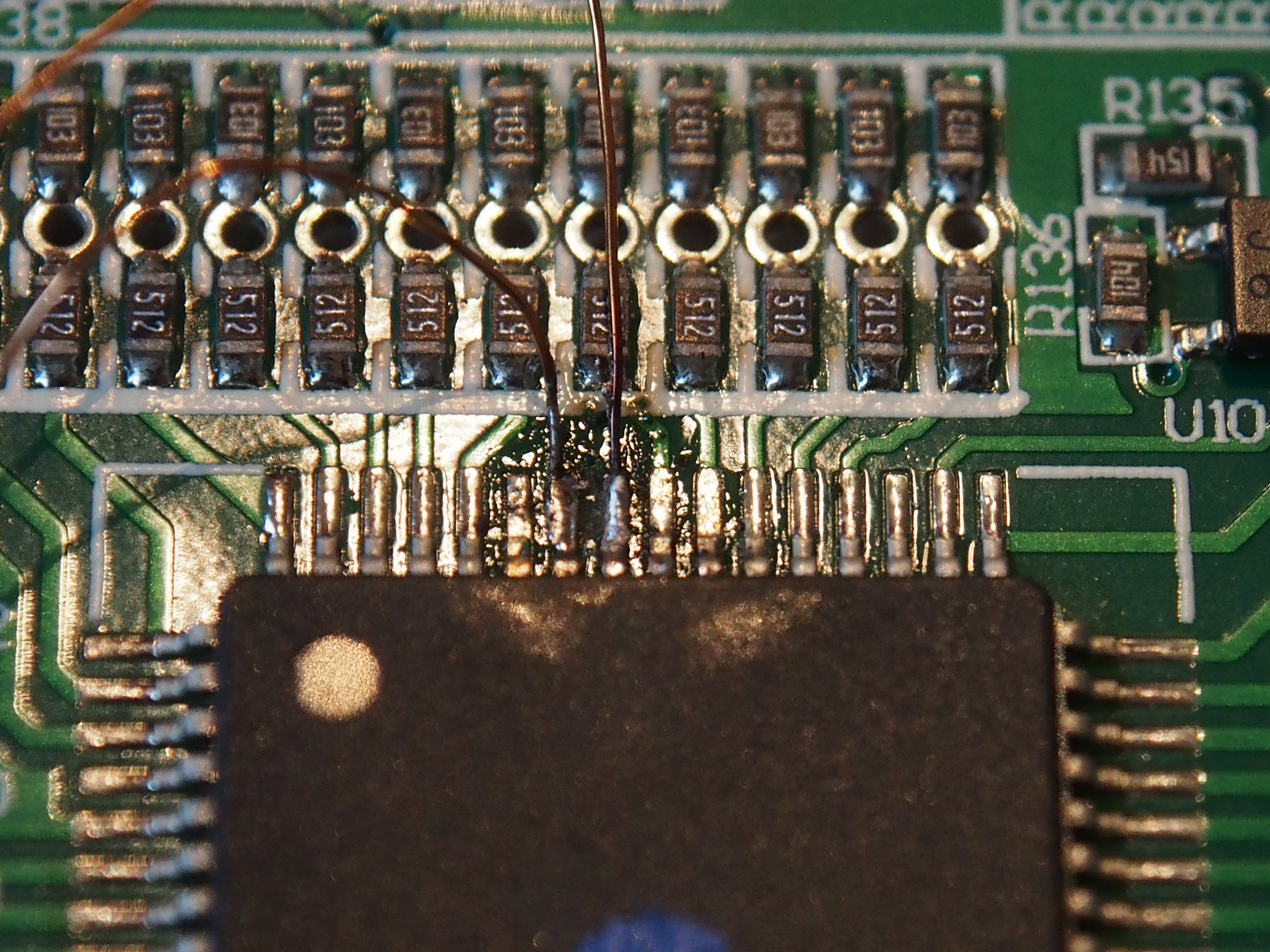
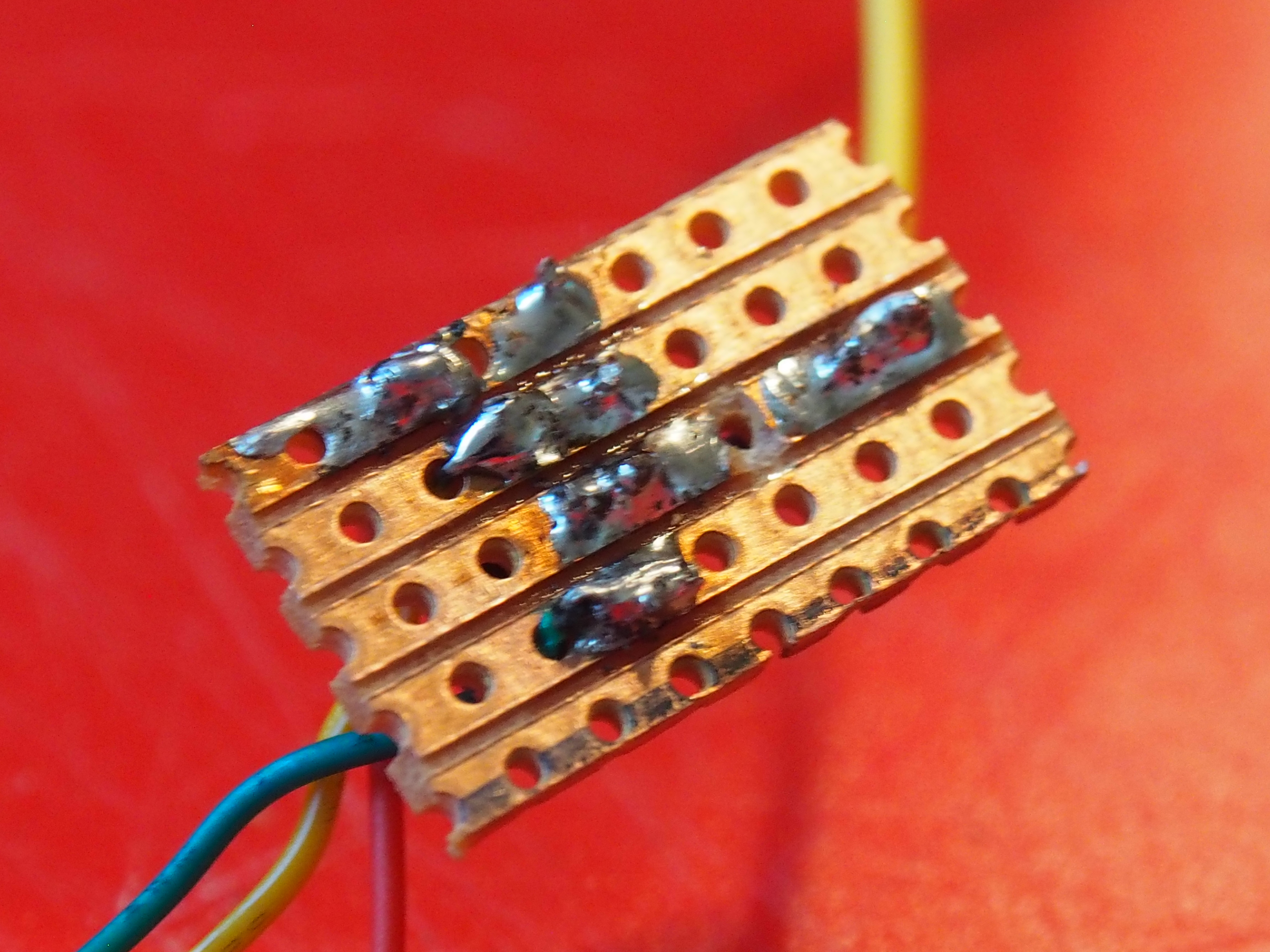
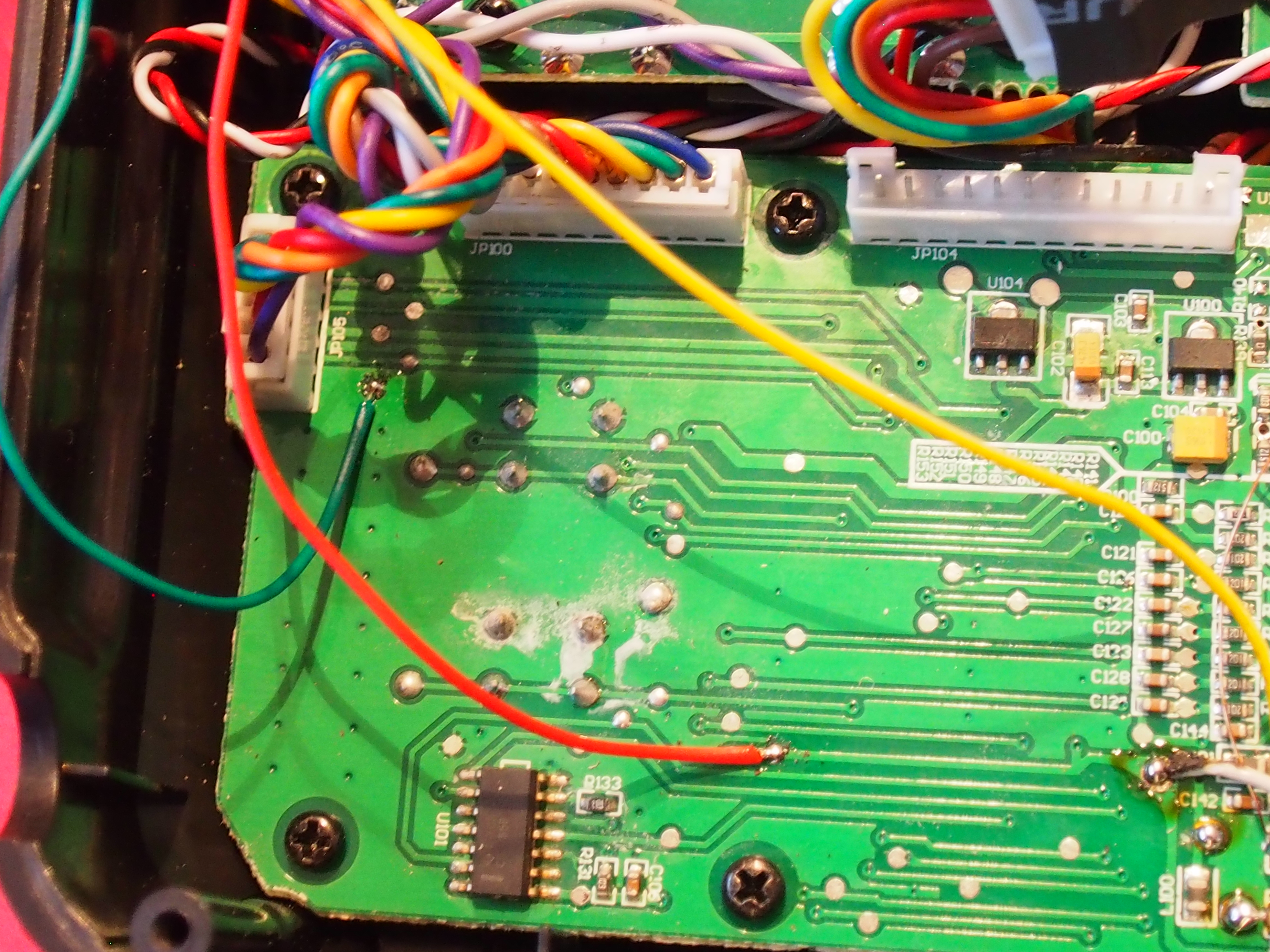
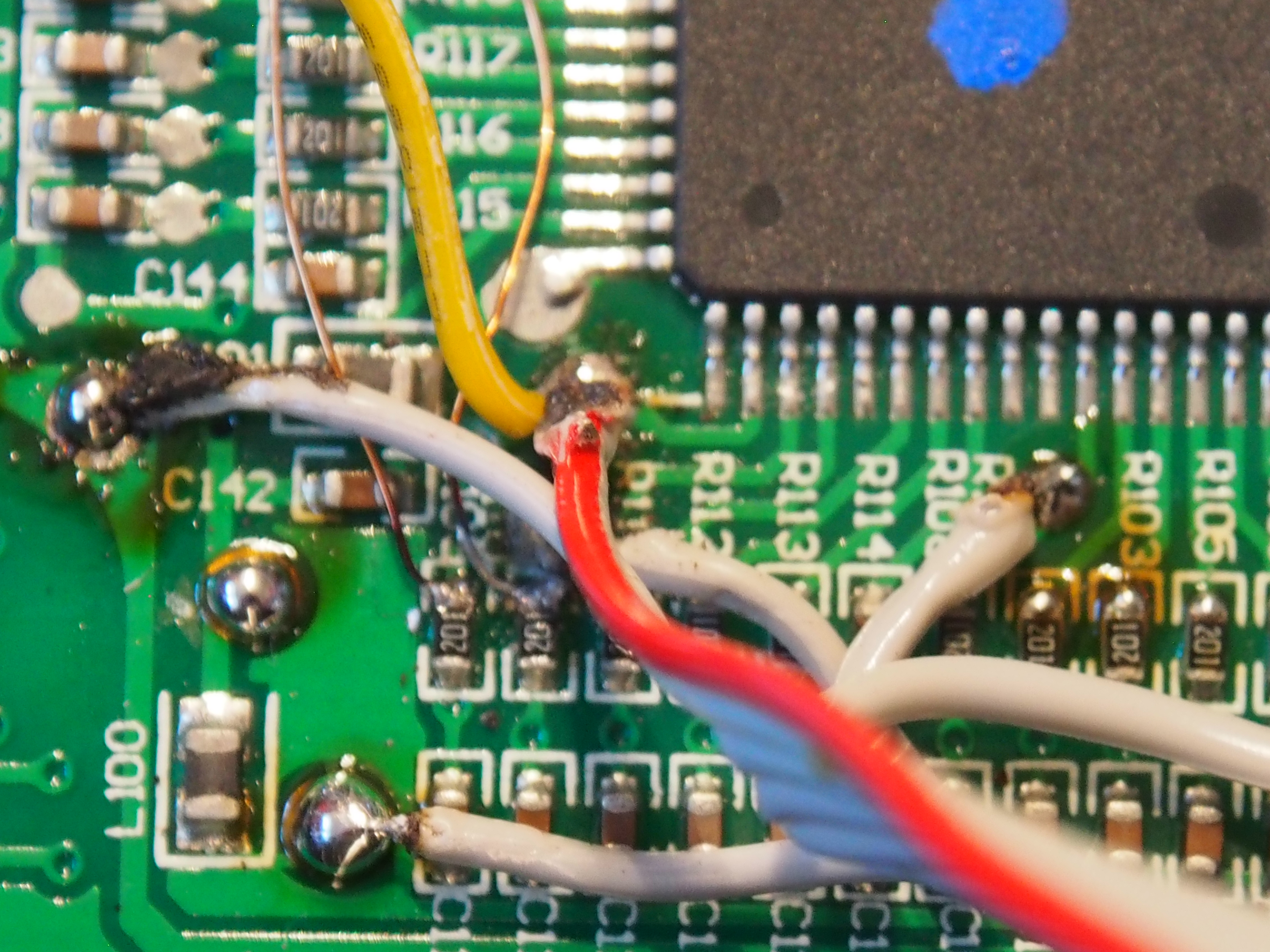
Like on the serial mod, you have to free up the UART pins on the 9x processor which are used by the two lower rear switches. In the images you can see that I did already connect the ISP Pins for flashing new Firmware to the 9x. Then I cut the traces for the most left resistors and connected them to the unused pins 41 and 42.
The two freed pins (RX) and (TX) are again getting connected to the ISP pin. Pin 2 will also be our S.Port pin.
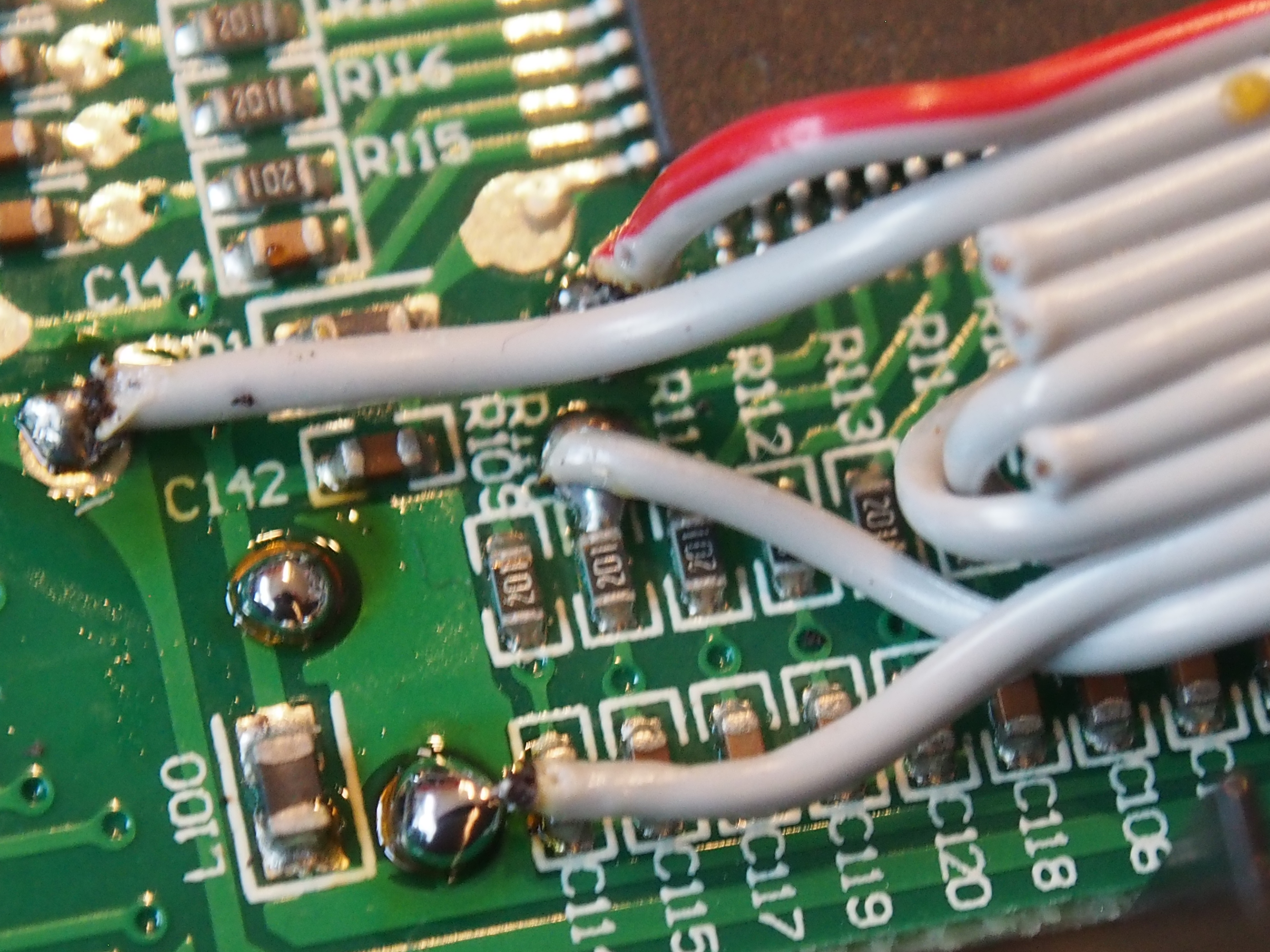
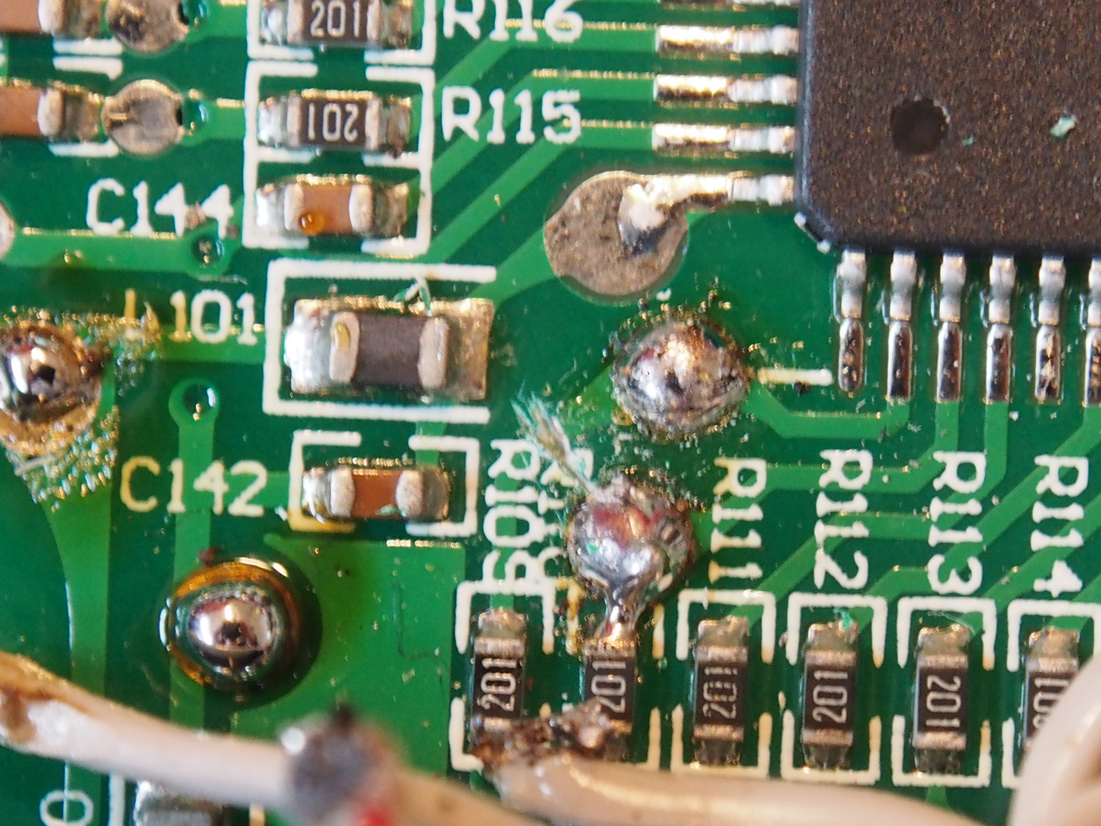

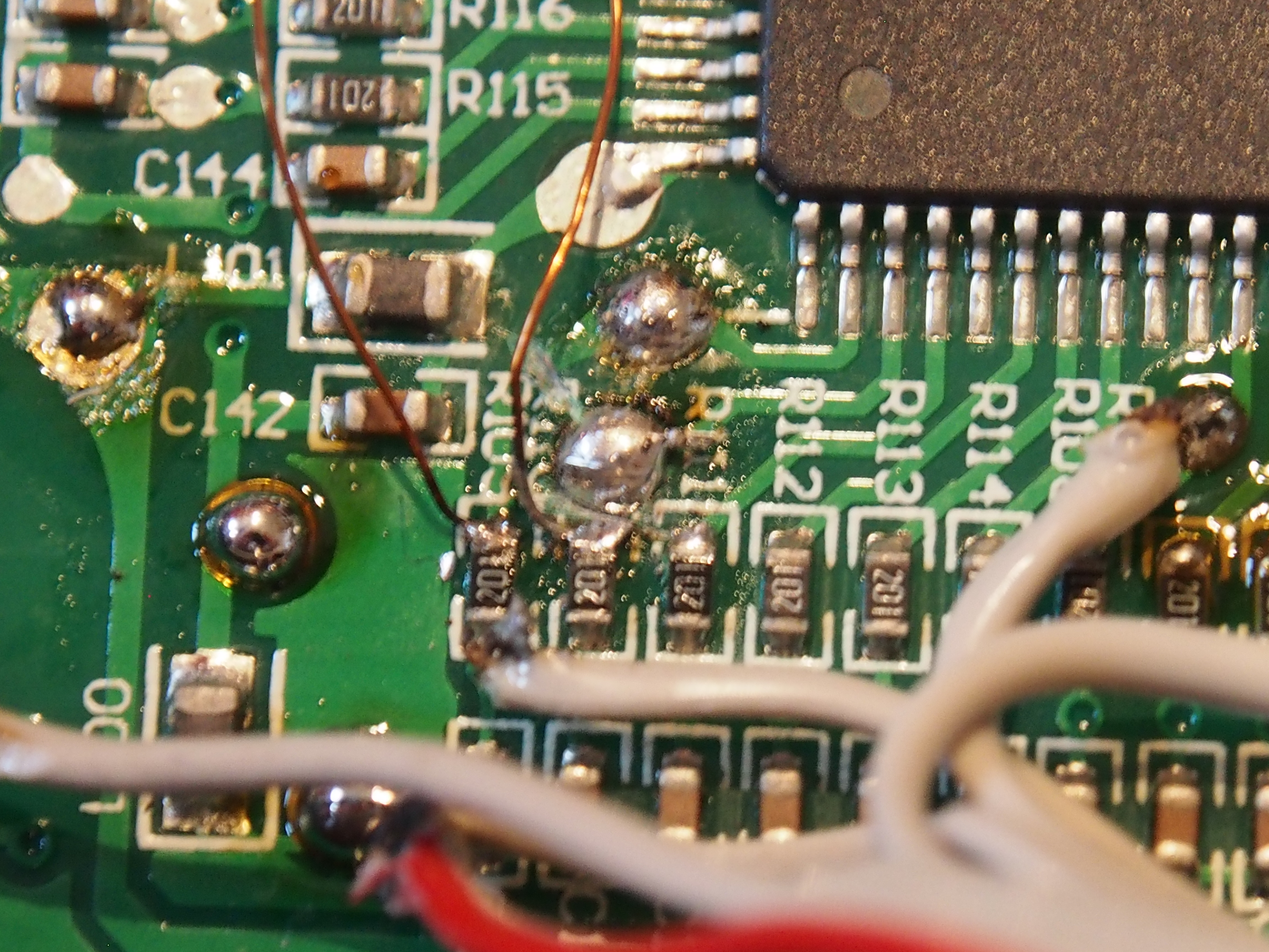
Important Note: Don’t do the mod like I did. Just desolder the two resistors and replace them with wired 120Ω one. So you don’t have to cut any traces and this makes soldering a lot easier.
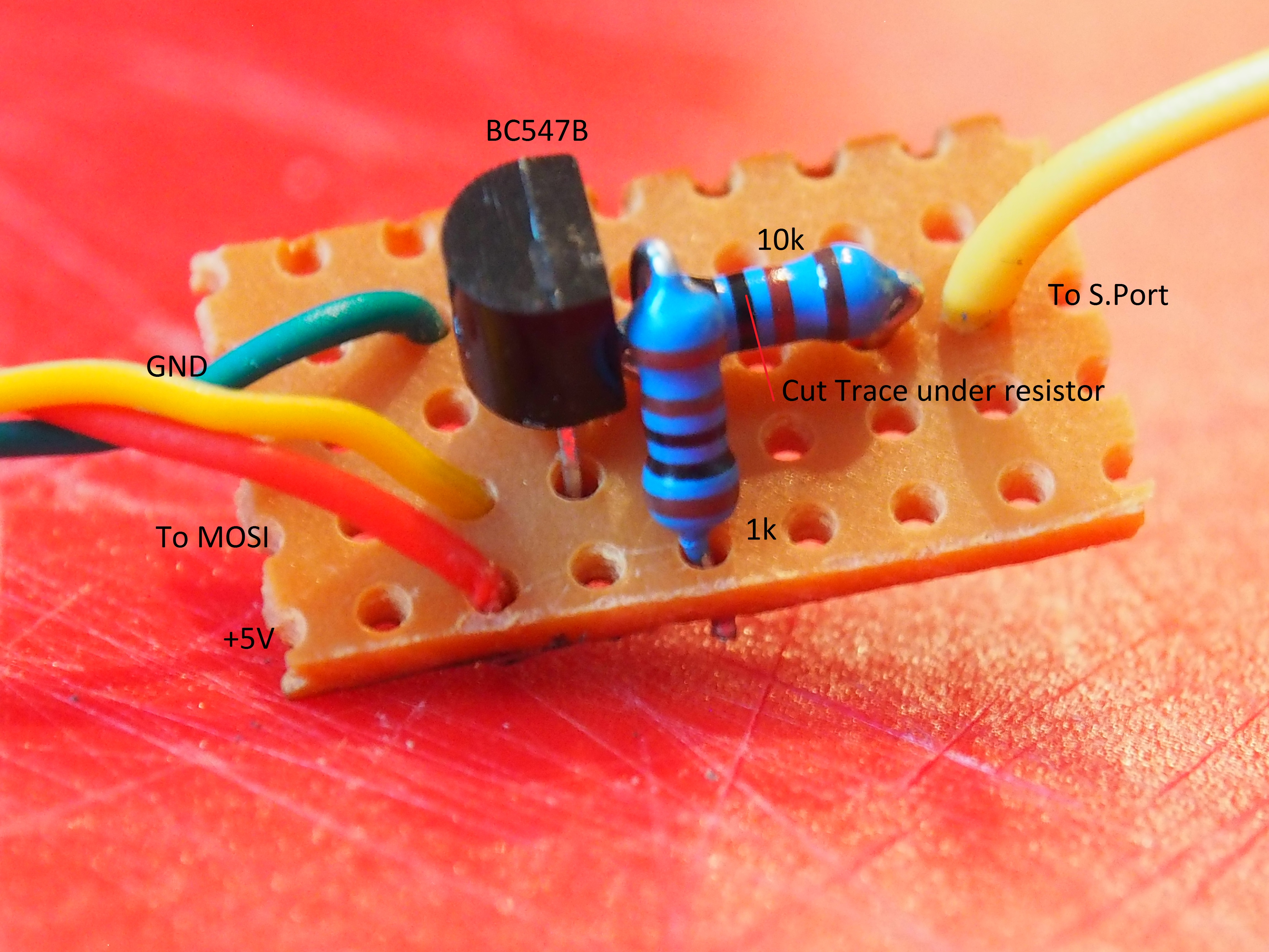
Now we need to create a little circuit for inverting the S.Port signal (not quite sure if this is necessary, but it worked for me!):

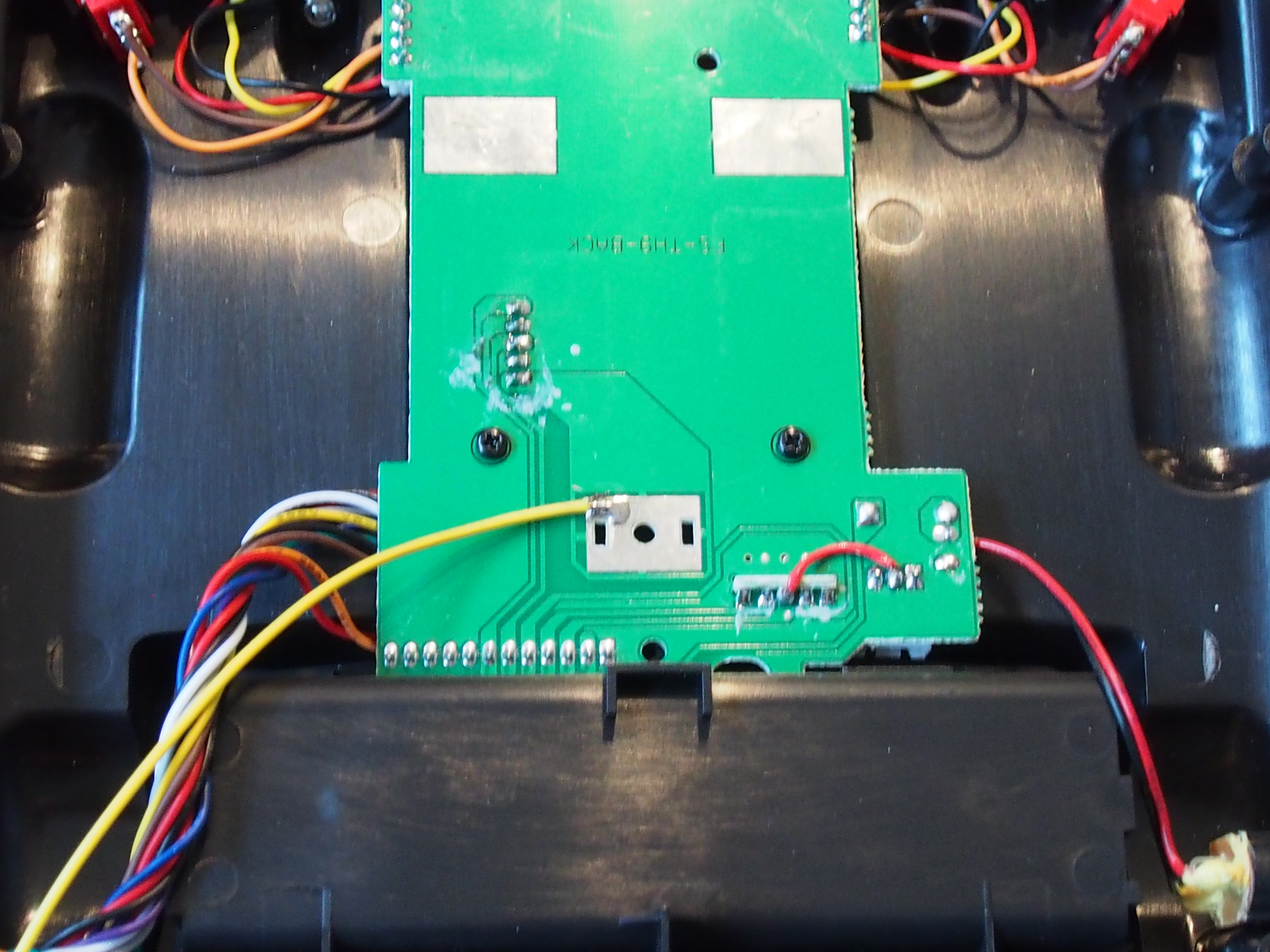
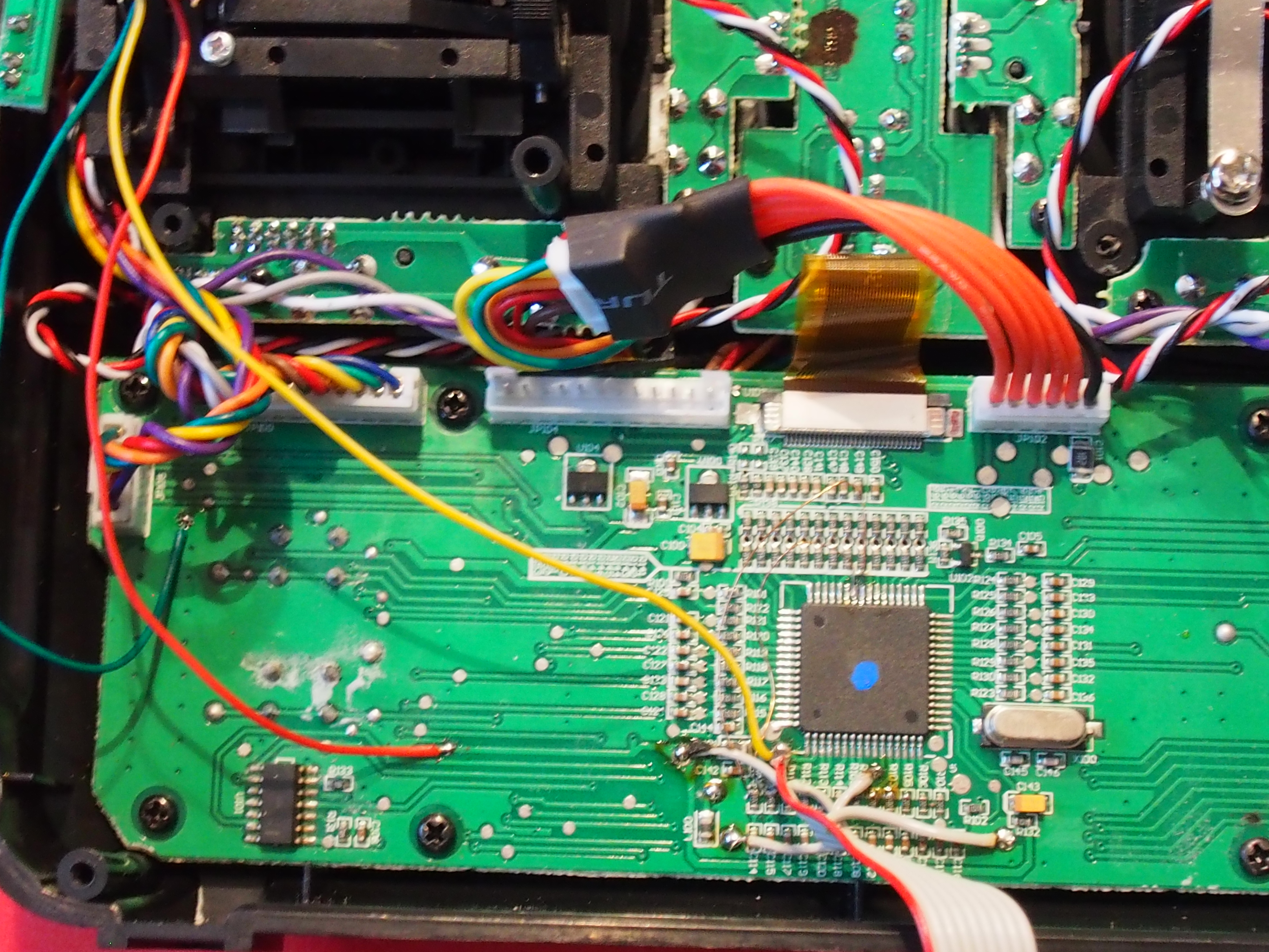
The S.Port is connected to pin 5 of the internal connector between the 9x and the module. This pin is unused and connected to the large solderpad. (Don’t know what it was supposed to be). I just connected the signal cable to the large solder pad.

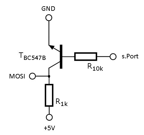
Now the inverter PCB hast to be connected to the processor. Signal to MOSI, power to 5V and GND to GND:
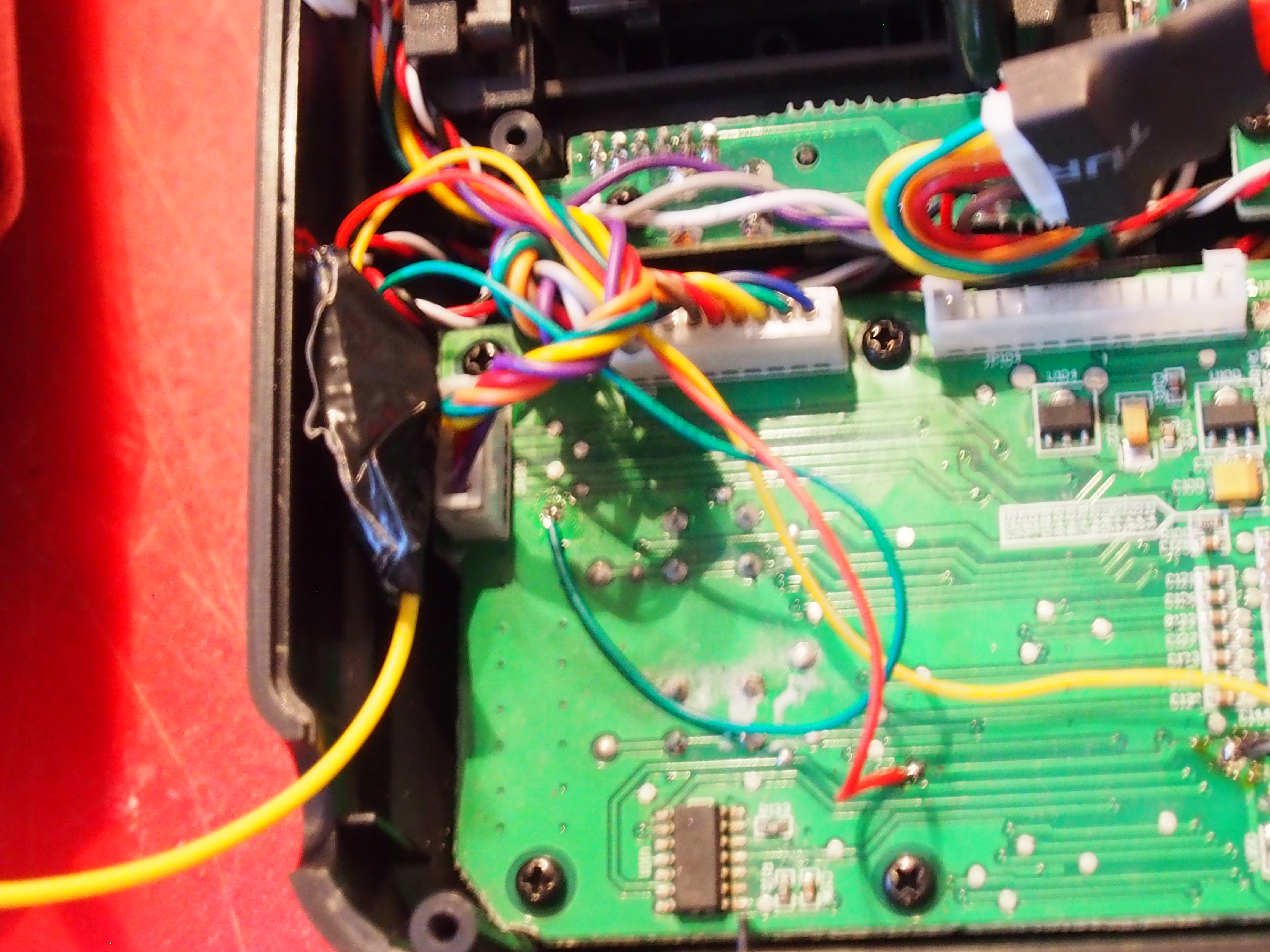
I also wrapped the PCB in duct tape to insulate it.
That’s the hardware side.
I used the er9x Firmware in the FrSky version wich uses the changed switch pins and enables telemetry. You can download the firmware and the flashing utility from the er9x webside. Remember to save / write down your settings before flashing.
To get the 9x to listen to S.Port instead of RX/TX, you have to set the protocol to PXX. Now you should already be able to see the RSSI values.
REMEMBER to rebind the receiver if you switched from another protocol to PPX.
13 replies on “Telemetry mod for the Turnigy 9x an FrSky XJT Module”
[…] the Telemetry mod of the Turnigy 9x, the air-side has to be able to communicate, […]
thanks for sharing ! how many watt your resistor in inverter board? do you have schematics for that board?
Hi, thanks for your interest.
The resistors are 1k and 10kΩ. Do you really mean Watt?
That are just signals, so there is very few current. 1/4 Watt is more than enough.
I just added the schematics for you 😉
This looks great and hopefully it might work for me too when I try this in a few days once my XJT module arrives, thanks for the guide since so many others just say to do the DJT mod which looks much more complicated.
Hi Jens, thank you for this explanation! I’ve made your mod so far, but unfortunately I’m still not getting the telemetry values on my 9x 🙁
Could you please explain where on the 9x you set the protocol to PXX? I’ve found only PPM and PPM16…
Hi, you need firmware on the 9x that is capable of reading the telemetry data.
I am using the telemetry-version of er9x.
Hello,
I followed your article to mod my turnigy 9x ’64 with xjt telemetry.
Everything is allright, but I don’t know how to change protocol to pxx, the trim left & power on just show a grambled screen.
I set the protocol to XJT D16 on my model, but the only thing that show up is the rssi and swr.
Anything I forgot ?
Thanks,
Finally found the hardware menu, but there is no pxx setting.
But still no reading of anything else than rssi & swr.
What can I do ?
Hi Alex,
if you can see the RSSI and SWR values, your settings on the 9x are correct.
All telemetry data from the XJT are sent the same way, this includes RSSI an SWR.
You need to send the correct S.PORT data to the receiver (which actually is the transmitts the telemetry).
Hi,
I think I’ve followed your instructions correctly since I have the rerouted switches working and have the inverter wired up but I dont get any values for swr or rssi, both are 0 and I have the protocol set to XJT, bound to an XSR. Any clue on what could be wrong?
This is on a m128 version of the 9X if that could make a difference.
Thanks for the guide so far 😀
Hi Aadi,
are you sure that your inverter is build correctly and working?
What are your protocol settings on the transmitter?
The only advice I can give you is just to sleep one night over it and than double check all steps again.
You could also try playing with the protocol settings (PPM8,PPM16,PXX-D8/D16,…) and check if there is any difference.
Hi Jens,
I tried rebuilding the inverter and using a MAX3232 chip instead but neither gives any reading in both D8 and D16 mode, I also checked with a multimeter on the xjt but there seems to be no output (0V) on the s.port pin but there is 0.25v on the txd pin. connecting to either still gives no value though, what should the voltge on the s.port pin be? or can you check on yours if you have time?
Thanks again
PS. i get the xjt option instead of PXX but the bind and range functions do make the xjt change mode and flash/beep
Hi again Jens,
I wasn’t able to get it working, but I did try using my xjt module in an unmodified Taranis and it still doesn’t get any telemetry values :/ would you know if this means that the module is faulty?