Categories
Electronic upgrades

External Antenna for Logitech G930 headset

My Logitech G930 is a very cool headset but sometimes has little connection problems.

The solution offered by logitech is to change the frequency but in my case the problems seams independent to the frequency.
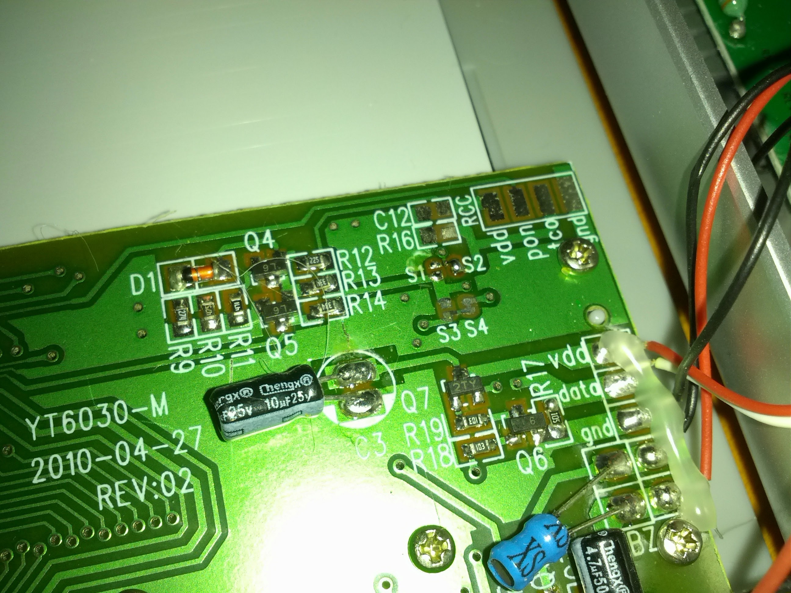
I have some 2,4 Ghz antenna stuff from older WiFi projects lying around and decided to take a clother look to the transmitter.
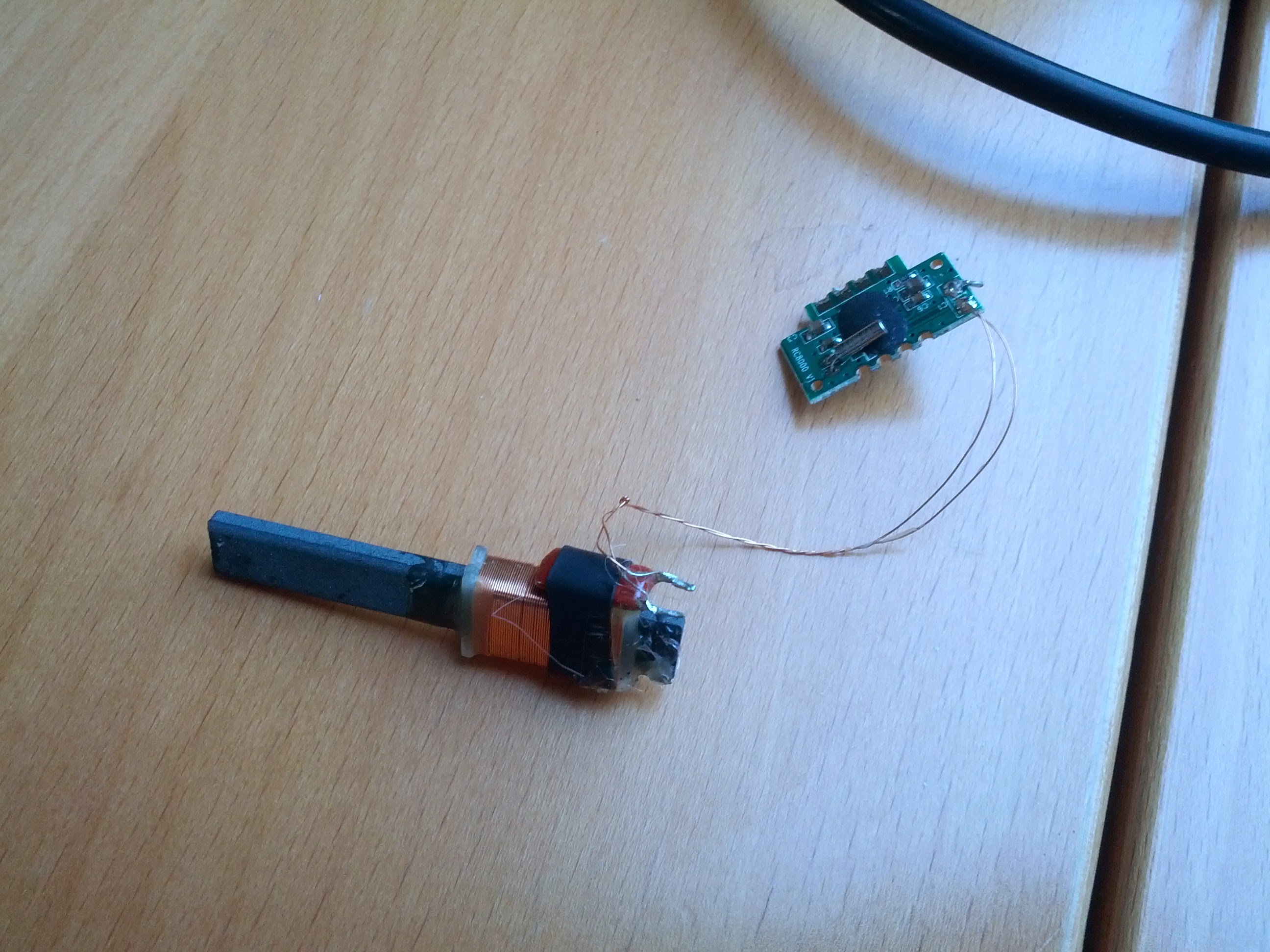
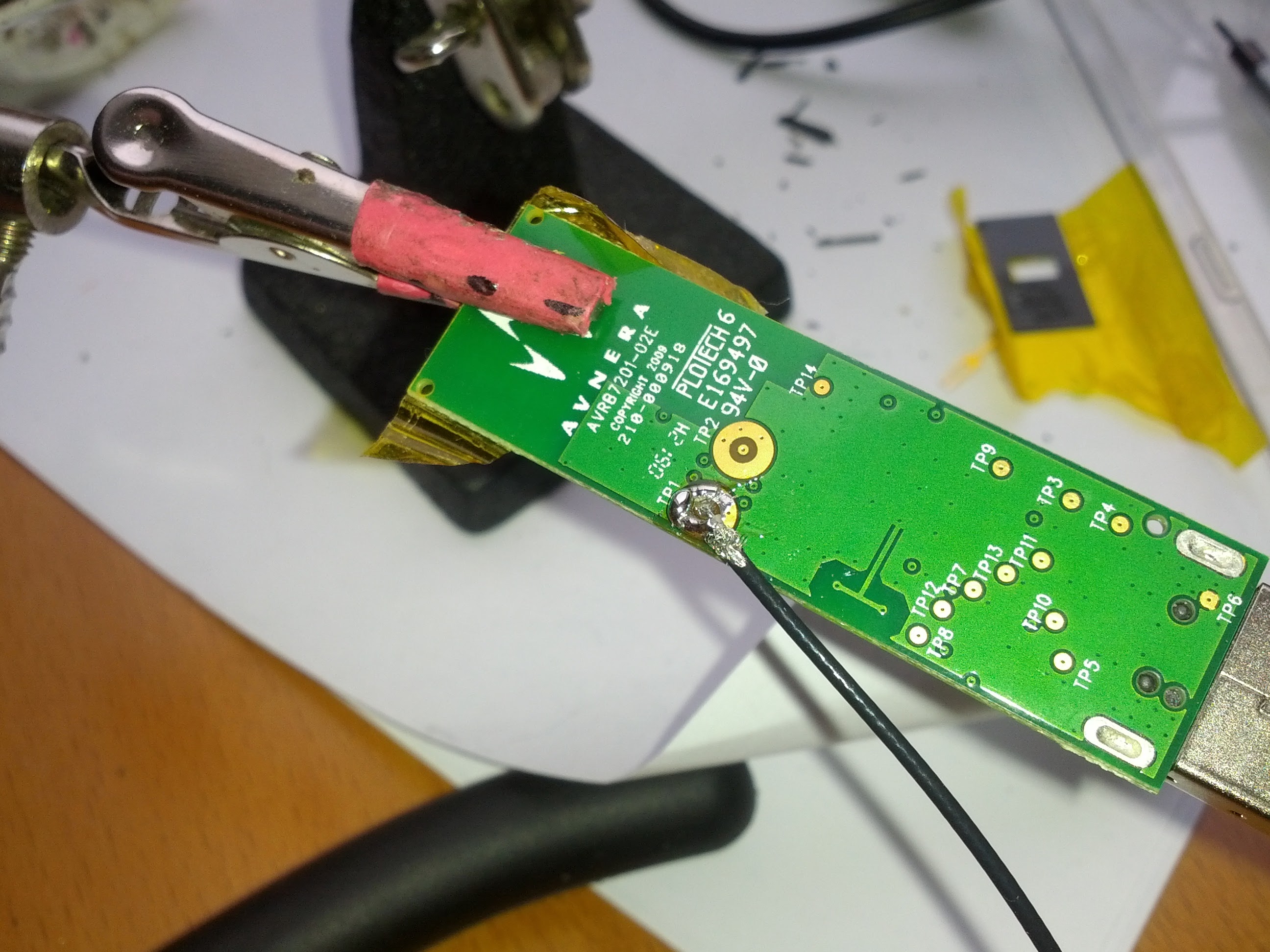
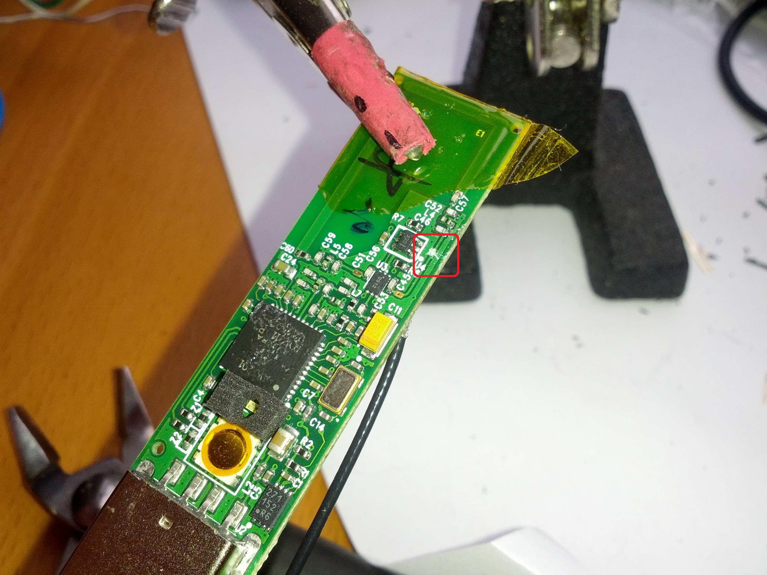
What I found are two PCB-antennas and two coax test points, so i took a RP-SMA pigtail, connected it to one of the test points, cut the connection to the PCB-antenna and attached it on the casing:

  • IMG_20140331_135829
  • IMG_20140331_140523
  • IMG_20140331_135836
  • IMG_20140331_141100
  • IMG_20140331_143016

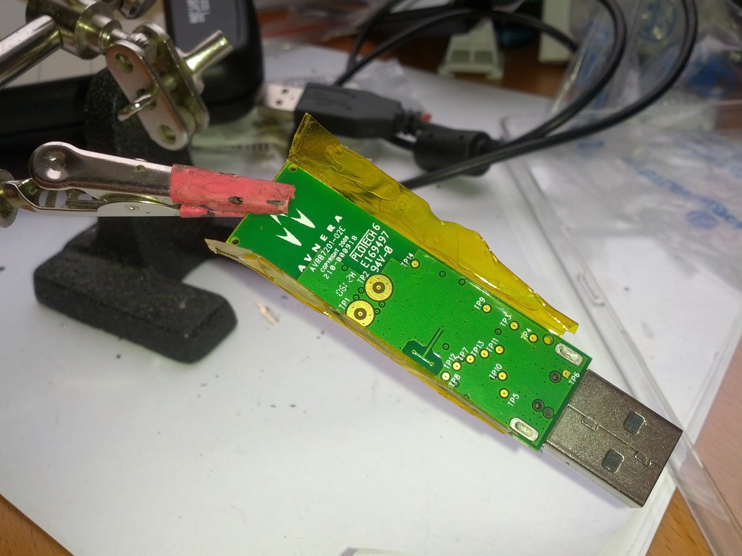
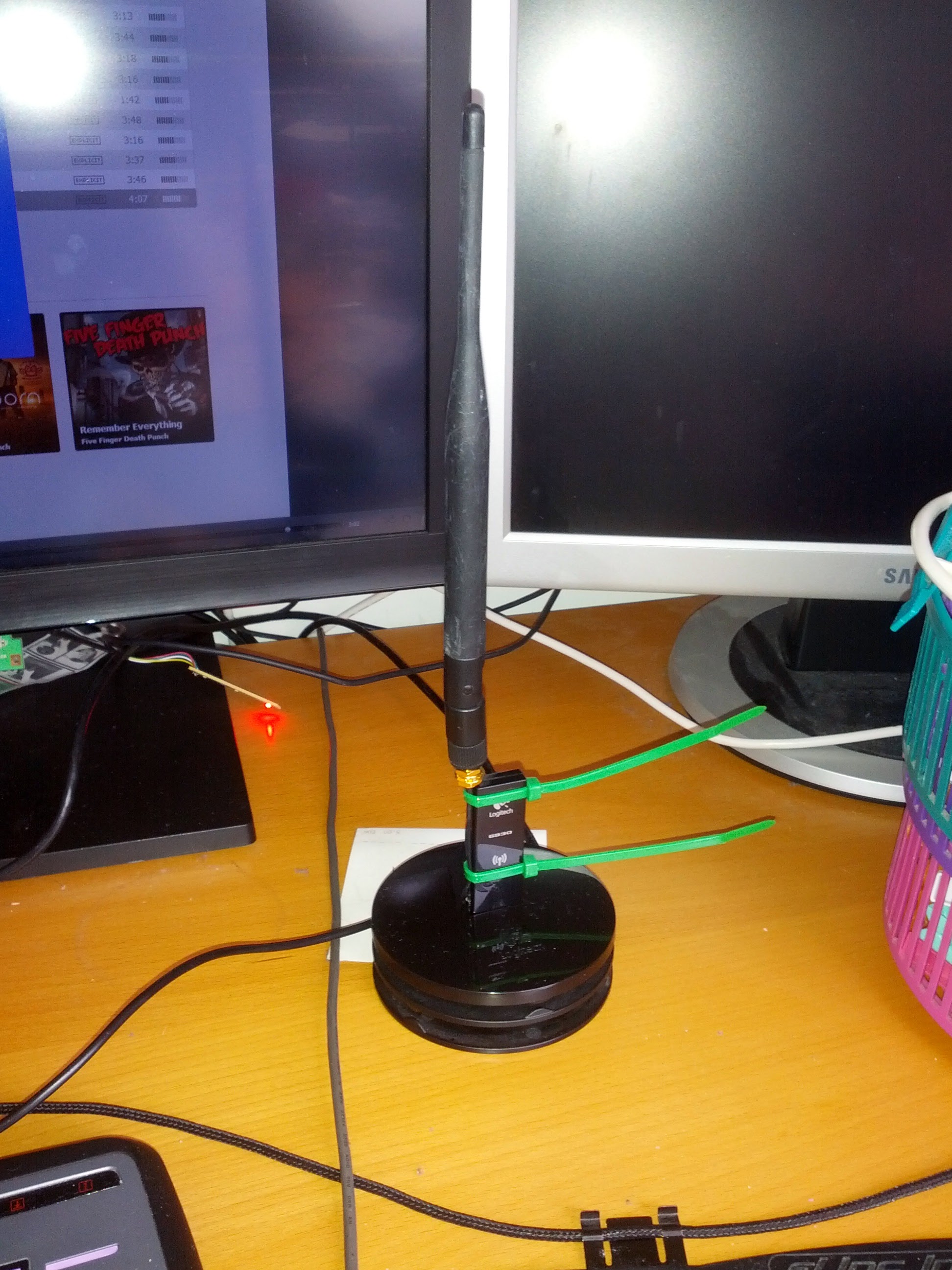
I can’t yet say if the connection problems are solved with this, but the range is significantly better with the antenna!

There was two antennas inside the transmitter and I have no idea if they are diversity or one sends and the other receives or what they are for.
But when I have another matching pigtail in hands, I will connect the other one too…

Categories
Electronic upgrades

Retrofit radio controlled clock

Last sunday, germany switches to the daylight saving time again, so i needed to adjust some clocks.

We had a weathers station with wireless temperature and humidity sensors that has a clock which needs to be adjusted manuall while most of that weather stations have radio controlled clocks integrated.
Even my very cheap weather receiver which i got from a giveway and was only used to analyze the wireless temperature signal has a time receiver.

So i wondered if it is possible to put the receiver from the cheap weather station in the one we are using. Quickly opened it and found four empty soldering pads labled “RCC” – maybe radio controlled clock or something like that. Also the four pads itself are labled:

GND – Ground
VDD – Voltage source (3V)
PON – Power on Signal (3V)
TCO – TimeCOntrol? At least a data pin..

The labeling matches with the sensor, so i simply connected it:

  • IMG_20140330_140224
  • IMG_20140330_140237
  • IMG_20140330_140904
  • IMG_20140330_140207
  • IMG_20140330_140216
  • IMG_20140330_141438

Near the connector are two soldering Jumpers (S1 and S2) which are explained on the PCB and must be switched from S1 to S2.
Also there are two empty component places, usually used for the receiver which doesn’t exist on the source PCB:

R16: Pull-down resistor for the PON signal. This is already implemented in the receiver module
C12: Filter capacitor for the data signal – maybe not needed.

So both stay empty.

The case has already mounts for the antenna where my antenna exactly fits in!

At least everything is put back together and six minutes later:

  • IMG_20140331_105247

The time is synced! And again one less clock to adjust!